Uses the smallest and cheapest 32 bit CPU to generate 3D graphics and sound.
The RBox is a game console that is simple enough to build on the prototype area of a dev kit; no pcb required just a crystal, a few capacitors and resistors.
Features:
320×240 composite or s-video output generated entirely in software
256 colors with standard palette, up to 8k colors
8 bit 15khz stereo audio
~$1 Analog joystick
~$1 CPU
A bit of history…
Ever since the Atari VCS generated video by Racing the Beam i have wanted to build something that generates video on the fly. There have been lots of great diy examples of this in the intervening years (Rickard Gunee’s Picpong and SX Tetris, the lovely Uzebox) but the arrival of the ARM Cortex M0 parts from NXP rekindled my interest. The NXP LPC111X family is smallest 32 bit CPU. It is an ARM Cortex M0, the same device I used in the Wikipedia reader. This family of devices starts at under $1.
The LPC111X parts have ample horsepower for black and white video, as many less powerful chips have done in the past. At a max clockspeed of 48mhz they require 2 clocks to access memory or gpio so you could write a blit loop fast enough for 320 horizontal resolution (each pixel at 320×240 takes 8 cpu clocks, enough time for read/palette lookup/write/test/loop). Add a couple of resistors for a DAC, add sync pulses and you are in business. Overclock to 57.27272 and then you are a multiple of the chroma carrier and can generate colorburst and manipulate chroma phase: Now I had nice color bars but it wasn’t clear how generalize this to a practical system that could be programmed to generate interesting and useful images.
The real breakthrough came when I realized I could re purpose SPI to manipulate chroma phase while the cpu used gpio to write luma. SPI also has a 16 byte fifo on these parts which allowed chroma writes to be queued relieving pressure on the luma timing. With SPI emitting bits at 1/2 the cpu clock rate I could get 8 bits per chroma clock, enough to do 8 different phases for 8 different hues. All the other 248 combinations of those bits generated other hues and levels of saturation, suggesting a palette of some sort might be useful.
Color generation solved, now I needed graphics. A frame buffer was out of the question: at 8 bits a 320×240 frame buffer is 75k. These devices have 2k to 8k total memory so another approach is needed. After fiddling with tiles (as in Uzebox) I eventually settled on a line buffer approach where the application sends individual lines to the video driver for display, allowing code that looks and feels like it is working with a framebuffer without the actual memory.
There are 2 pixel formats supported: 5 bits of luma with 3 bits of chroma index or 4 bits of luma with a 4 bit chroma index. The chroma indexes map to the actual 8 bit value emitted by SPI. The chroma palette can be changed every line allowing up to 8k colors on the screen at the same time. With 8 bit color filling the line buffer is simply a matter of dealing with 1 byte per pixel blitting and things like smooth scrolling become very simple.
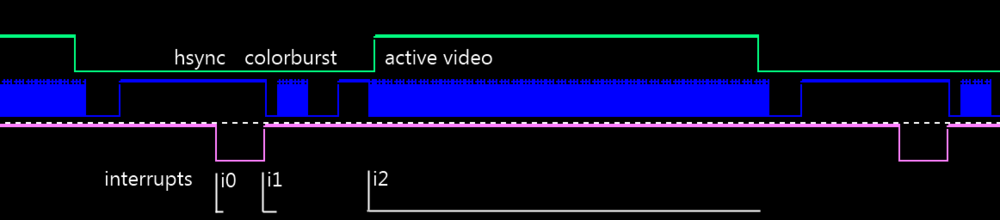
The video driver generates 3 interrupts per line: i0 at start of the line to pull hsync and emit an audio sample. 1 pcm sample gets emitted per channel per scanline at 15.7khz which is the line rate of ntsc. i1 happens at the end of hsync. The driver releases hsync and feeds the colorburst data into the SPI fifo then returns. The active video interrupt i2 actually emits the pixels and uses about 70% of the cpu.
Much as I love this CPU there were a few wrinkles. At this clockspeed, it needs 3 wait states to access flash. If you execute code from flash on this part you can never be sure when those wait states will slow you down: the same code may run at different speeds depending on its position in flash. Really bad if you are writing a blit loop that has really tight timing requirements like generating ntsc in software. The solution was to copy the critical routines to RAM where they run without any wait states.
Other devices like the Cortex M3 based LPC13XX and the LPC17XX have flash accelerators and single clock gpio writes. The LPC17XX also has DMA that makes all this sort of thing really easy – 640×480 component video should be possible. Although more expensive than the M0 parts, they are still ridiculously cheap.
About the demo video
Tile
Scrolling around a 8192×2048 map of a certain hedgehogs homeworld. The demo uses the analog joystick as input, features single pixel horizontal and vertical smooth scrolling and runs at at 60fps. The audio in the background (the music, not the leafblower) is coming from the device.
Particle
500 particles spraying at random from two sources over an animated background. The texture in the back is being generated every line by multiplying the luminance of a blob pattern by sin(y). Single cycle multiplies take a lot of getting used to; it is often faster to multiply than to use shift/add “optimizations”. 60fps.
3D
Platonic solids float over an animated 3D plane with weird patterns in the sky that gratuitously change color. The 3D models are rendered scanline by scanline and composited with the dynamically generated backgound. Once again, because we don’t have a frame buffer, we get 60fps with no tearing.
How to build
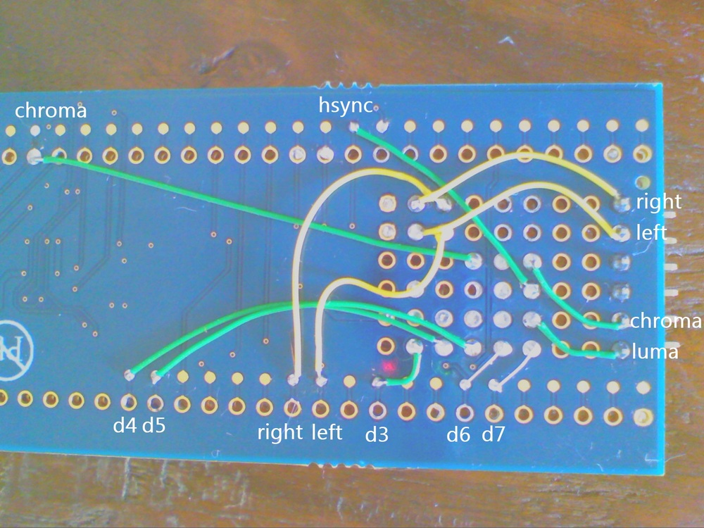
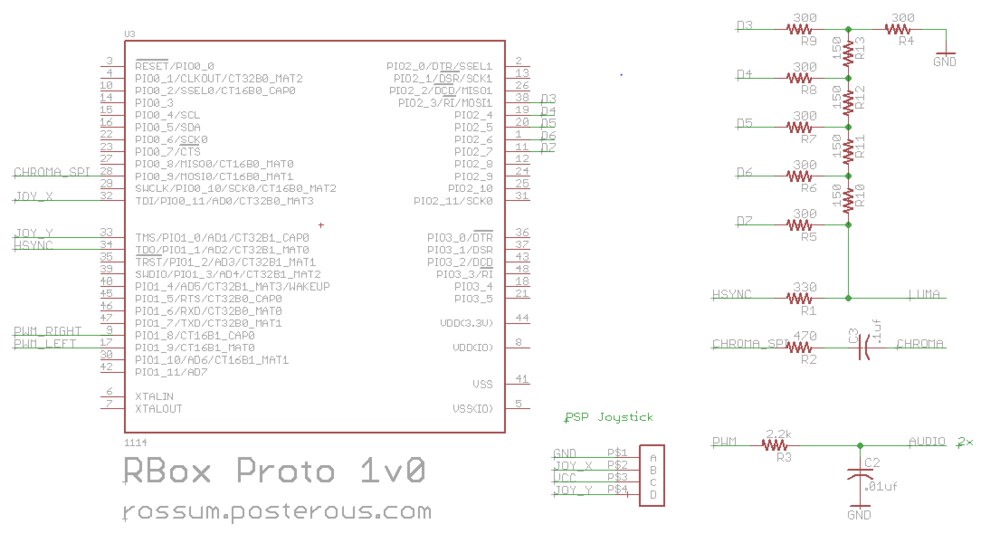
If you want to make your own I have included the schematic and the code. I built the prototype on a LPCXpresso devkit available at Digikey, you will need to replace the stock 12mhz with a very common 14.318mhz crystal. I bought a reel of these so if you can’t find one I will send you one. The analog joystick is a replacement part from a PSP. $1ish on ebay. The wiring photos are a little tricky to follow, check the schematics for a clearer version.
This is really impressive! Looks like a perfect candidate for a next-generation Uzebox. Are you going to release source code, or better yet, put up a tutorial on how you programmed this?
Ya, it says the code is available, but there doesn’t seem to be a link. I’ve been doing some work with the LPC1114 and LPC1313 and wouldn’t mind giving this a try. All of your projects have been impressive and fun.
I’m not squeemish about green wires. Is there a possibility of getting a few pictures of the Teeny AVR Media Thing – the Nanotouch? I think I have all the necessary parts, but getting them put together is another story. Please and thank you in advance.
msftianslenksan here, herryergacheffsan pointed me in your direction. i (literally) had a dream for a 70s retro bang-und-olufsenish 8/16bitish console shell, i gotta (won’t happen) mock it up at techshop i guess, and leverage RBoxy stuff! i dream of a new console that’s open, cheap, not meant to get anybody rich, and full of fun community and creativity. er, well, all based on other people’s free time, since i have none already.
How are you able to set 8 bit color + 4 bit luma per pixel at 320 horizontal pixel resolution ?
You are taking 8 cycles per pixel. Running the CPU at 57.7 MHz , the pixel clock will be about 7.1Mhz. But the color burst cycle is only 3.57 MHz which is half of 7.1 Mhz. This means that for every color burst cycle, there are 2 pixels on the screen. 8 bits are needed by SSP to complete one color burst cycle when its working at 28.6MHz. So 8 bits of chroma information for 2 pixels. Not one.
@spiky Thats exactly right: 8 bits of SPI per chroma clock, 2 luma samples per chroma clock. Luma resolution is 2x chroma resolution, so even though all pixels have luma and chroma information only even pixel chroma gets used. .
I wonder how the picture quality will be if composite video is used instead of s-video. I’ve got a LPC2148. I’ll dirty my hands with this sort of thing very soon.
We’d love a more detailed explanation describing how you could do that cool 3D stuff. With a line buffer, you hardly have about 1000 cycles to fill up 320 bytes.
I am very impressed by your work, I’ve been looking through your projects and code and have to say that your coding/design skills are *quite* impressive. Unfortunately, as I am nowhere close to your level of skill, reading through your code (though excellent it is) is quite difficult for me, and I (like spiky) would be very appreciative if you could explain how you use line buffering to draw meaningful shapes (e.g. the 3d shapes) on the screen. I have a lpc2148 hooked up to a uSD card and OLED screen, but unfortunately I haven’t been able to figure out a suitable method of drawing to the screen other than a frame buffer. However, as the 2148 only has 32 KB of memory, trying to hold 16 bit color for 128×128 pixels pushes me over the RAM usage. (The version of the OLED screen does not support 256 color mode). So I’d be very interested to learn more about how a line buffer works with graphic displays (really, how to draw effectively with a line buffer), as it would save me memory and be quite an interesting project. Any information you could provide, and/or resources you could point me to would be greatly appreciated! 🙂 The 3d shapes are really awesome, I’ve seen you do them on this and on your AVR based micro-touch which was quite impressive as well. You are incredibly talented, so I’m trying to learn as much as I can 🙂 Keep up the good (*great*) work!
How did you take care of interrupt jitter ? Even a jitter of a few cycles will mess up the display and completely mess up the chroma.
I tried displaying a few vertical lines on the Atmega32 and it was successful. I thought I should do this before attempting the same with ARM as I am more comfortable with atmega controllers. One problem I encountered with the atmega was Interrupt Jitter.To solve this,I put the controller to sleep before the interrupt arrived. This is not a very practical solution if I want to do anything other than display static objects. The other way I see is to use carefully timed assembly code comparing with the timer to remove the jitter. While this is possible in the Atmega, it will be a lot harder on the ARM7.
Can you give me a few tips to solve this issue ? Does cortex m0/m3 also pose the same problem of jitter ?
@spiky The M0 has a fixed interrupt latency so no jitter there; the real non determinism comes from flash wait states if you don’t execute from ram. The clever Uzebox deals with avr interrupt jitter by syncing the cpu to the clock when entering the interrupt. Check out uzeboxVideoEngineCore.s – great stuff.
If you don’t use the chroma pin, would the output be just black and white?
Also why is the Hsync going to the same resistor network as the 5 bits of luma output? Does the code generate the Hsync pulses independently while everything gets voltage OR’d at the end? I had read that there is a very peculiar voltage levels associated with front / back porches!
@Ben Nguyen If you don’t connect the chroma pin you will get lovely black and white; ntsc/pal/secam is just brilliant that way.
The 5 bits of luma are independent from the sync so the games don’t have to bother with it and you get a little more dynamic range. Black level is 300mv above sync.
I have an old black and white tv that I’ve been given permission to play with! However, I’m a little confused as to the voltages. The wiki for Monochrome Video, http://en.wikipedia.org/wiki/Analog_television , says:
“The luminance component of a composite video signal varies between 0V and approximately 0.7V above the ‘black’ level. In the NTSC system, there is a blanking signal level used during the front porch and back porch, and a black signal level 75mV above it”
So if I read that correctly, sync is 0v, “porch” is .625v, black is .7v, and white is 1v
But you have 0, .3v and 1v, which is a bit different, and doesn’t include the porch.
Could this be a “PAL” vs. “NTSC” difference? Or do newer tvs have different voltage standards?
Hey Rossum. I greatly admire what you have accomplished. Quick question – would it be possible to run code from an external memory source? Think a crude DIY atari 2600 cartridge type of system.
Hi Rossum – I’m a journalist looking to do an interview about the Rbox – is there an email address I can get you on? Mine is ben.sillis AT republicpublishing.co.uk


it looks grate! :D. I wonder if 1343 is faster, would i need another crystal?
Nice Work, good Idea to Use the Analog-Pad of the PSP. Did you had any Problems Solidering it, usually you have on the PSP a Pice of “Leitergummi” .
Awesome job Rossum, once again you astound us with your code wizardry!
Very cool, ill might even try this one out my self.
This is really impressive! Looks like a perfect candidate for a next-generation Uzebox. Are you going to release source code, or better yet, put up a tutorial on how you programmed this?
Ya, it says the code is available, but there doesn’t seem to be a link. I’ve been doing some work with the LPC1114 and LPC1313 and wouldn’t mind giving this a try. All of your projects have been impressive and fun.
That is awesome. It’s amazing to see hobbyists build hardware that once would have taken a team of engineers.
Any lcd screen suitable for easyly attaching?
pics are not showing up .. hope you can fix them
working now 🙂 Keep up the good work!
@Urko, Check out his wiki device last post to see an LCD on the LPCExpresso board.
Hi, I second the comment above – can you post the code – very interested in using this in a visualization project.
Just posted the code on https://sourceforge.net/projects/rbox/. Let us know if you make something!
What is this song? So familiar…
@Dwight Trollinger
I think it is Cold Play with Clocks
Actually the LPC1102 is the smallest 32-bit ARM microcontroller 🙂
The demo has music already – “Clocks” playing in a loop. The hardware will do stereo 8 bit at 15khz so better music + effects are possible/likely
words… can.. not… describe .. LIKE!
I’m not squeemish about green wires. Is there a possibility of getting a few pictures of the Teeny AVR Media Thing – the Nanotouch? I think I have all the necessary parts, but getting them put together is another story. Please and thank you in advance.
msftianslenksan here, herryergacheffsan pointed me in your direction. i (literally) had a dream for a 70s retro bang-und-olufsenish 8/16bitish console shell, i gotta (won’t happen) mock it up at techshop i guess, and leverage RBoxy stuff! i dream of a new console that’s open, cheap, not meant to get anybody rich, and full of fun community and creativity. er, well, all based on other people’s free time, since i have none already.
How are you able to set 8 bit color + 4 bit luma per pixel at 320 horizontal pixel resolution ?
You are taking 8 cycles per pixel. Running the CPU at 57.7 MHz , the pixel clock will be about 7.1Mhz. But the color burst cycle is only 3.57 MHz which is half of 7.1 Mhz. This means that for every color burst cycle, there are 2 pixels on the screen. 8 bits are needed by SSP to complete one color burst cycle when its working at 28.6MHz. So 8 bits of chroma information for 2 pixels. Not one.
@spiky Thats exactly right: 8 bits of SPI per chroma clock, 2 luma samples per chroma clock. Luma resolution is 2x chroma resolution, so even though all pixels have luma and chroma information only even pixel chroma gets used. .
Thanks for the clarification.
I wonder how the picture quality will be if composite video is used instead of s-video. I’ve got a LPC2148. I’ll dirty my hands with this sort of thing very soon.
We’d love a more detailed explanation describing how you could do that cool 3D stuff. With a line buffer, you hardly have about 1000 cycles to fill up 320 bytes.
I am very impressed by your work, I’ve been looking through your projects and code and have to say that your coding/design skills are *quite* impressive. Unfortunately, as I am nowhere close to your level of skill, reading through your code (though excellent it is) is quite difficult for me, and I (like spiky) would be very appreciative if you could explain how you use line buffering to draw meaningful shapes (e.g. the 3d shapes) on the screen. I have a lpc2148 hooked up to a uSD card and OLED screen, but unfortunately I haven’t been able to figure out a suitable method of drawing to the screen other than a frame buffer. However, as the 2148 only has 32 KB of memory, trying to hold 16 bit color for 128×128 pixels pushes me over the RAM usage. (The version of the OLED screen does not support 256 color mode). So I’d be very interested to learn more about how a line buffer works with graphic displays (really, how to draw effectively with a line buffer), as it would save me memory and be quite an interesting project. Any information you could provide, and/or resources you could point me to would be greatly appreciated! 🙂 The 3d shapes are really awesome, I’ve seen you do them on this and on your AVR based micro-touch which was quite impressive as well. You are incredibly talented, so I’m trying to learn as much as I can 🙂 Keep up the good (*great*) work!
One more question.
How did you take care of interrupt jitter ? Even a jitter of a few cycles will mess up the display and completely mess up the chroma.
I tried displaying a few vertical lines on the Atmega32 and it was successful. I thought I should do this before attempting the same with ARM as I am more comfortable with atmega controllers. One problem I encountered with the atmega was Interrupt Jitter.To solve this,I put the controller to sleep before the interrupt arrived. This is not a very practical solution if I want to do anything other than display static objects. The other way I see is to use carefully timed assembly code comparing with the timer to remove the jitter. While this is possible in the Atmega, it will be a lot harder on the ARM7.
Can you give me a few tips to solve this issue ? Does cortex m0/m3 also pose the same problem of jitter ?
@spiky The M0 has a fixed interrupt latency so no jitter there; the real non determinism comes from flash wait states if you don’t execute from ram. The clever Uzebox deals with avr interrupt jitter by syncing the cpu to the clock when entering the interrupt. Check out uzeboxVideoEngineCore.s – great stuff.
Hi,
If you don’t use the chroma pin, would the output be just black and white?
Also why is the Hsync going to the same resistor network as the 5 bits of luma output? Does the code generate the Hsync pulses independently while everything gets voltage OR’d at the end? I had read that there is a very peculiar voltage levels associated with front / back porches!
@Ben Nguyen If you don’t connect the chroma pin you will get lovely black and white; ntsc/pal/secam is just brilliant that way.
The 5 bits of luma are independent from the sync so the games don’t have to bother with it and you get a little more dynamic range. Black level is 300mv above sync.
I have an old black and white tv that I’ve been given permission to play with! However, I’m a little confused as to the voltages. The wiki for Monochrome Video, http://en.wikipedia.org/wiki/Analog_television , says:
“The luminance component of a composite video signal varies between 0V and approximately 0.7V above the ‘black’ level. In the NTSC system, there is a blanking signal level used during the front porch and back porch, and a black signal level 75mV above it”
So if I read that correctly, sync is 0v, “porch” is .625v, black is .7v, and white is 1v
But you have 0, .3v and 1v, which is a bit different, and doesn’t include the porch.
Could this be a “PAL” vs. “NTSC” difference? Or do newer tvs have different voltage standards?
Hey Rossum. I greatly admire what you have accomplished. Quick question – would it be possible to run code from an external memory source? Think a crude DIY atari 2600 cartridge type of system.
hey i was wonderin how did you hook that up to the screen.can you send me a detailed diagram on how to make this.
also where do you hook up the pos and neg
I am mighty impressed with your work on rbox. Its just too amazing. We would like to send you one of the base boards that we designed for Xpresso. http://shop.ngxtechnologies.com/product_info.php?cPath=21&products_id=96
Let me know your shipping address and I will get you one. Our board has audio o/p and VGA support.
I was able to build the project and get the audio working on our board :), just wondering what would it take to get VGA out instead of s-video
—
Warm regards
Ashwin
Director, NGX Technologies Pvt. Ltd.
http://shop.ngxtechnologies.com/
Hi Rossum – I’m a journalist looking to do an interview about the Rbox – is there an email address I can get you on? Mine is ben.sillis AT republicpublishing.co.uk
Pingback: Progress, and some new ideas – Weka OSD