I finally got around to assembling a stand alone version of the RBox. As some of you correctly noted building a videogame for the price of a latte that depends on a $30 dev kit is cheating a bit. This version is self contained and while not practical or useful it is at least fun to build.
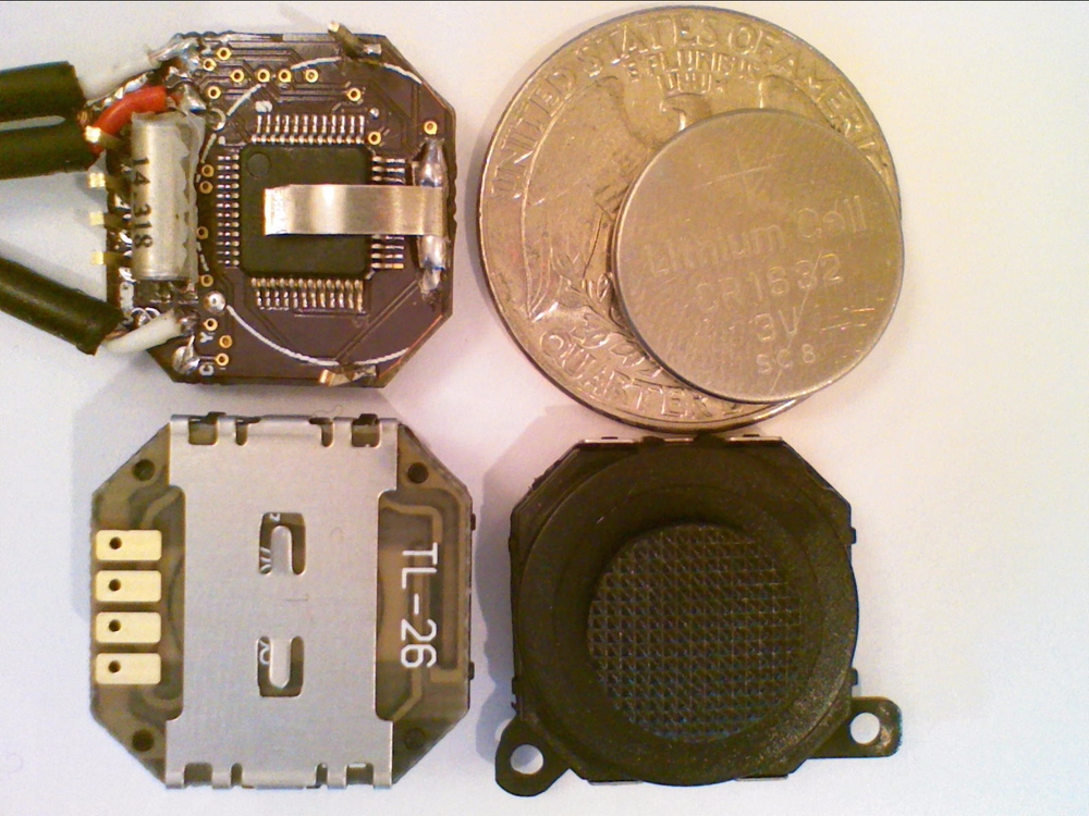
The design sandwiches a lithium button cell between the psp joystick and the pcb. It adds a single button that serves as both the power switch and a fire button. 2 axis control + fire may seem a modest level of input but modern standards but if it was good enough for Atari is is good enough for me.
Thin bendy metal on top of the cpu and on the bottom of the joystick provide a suprisingly effective friction fit for the CR1632 battery. Don’t try to solder directly to the metal on the bottom of the joystick. When running a game and playing audio the device uses about 28ma so I get about 4 hours of continuous use from the CR1632. Feel free to use a CR1616 or CR1620 for a slimmer look and more frequent battery replacement.
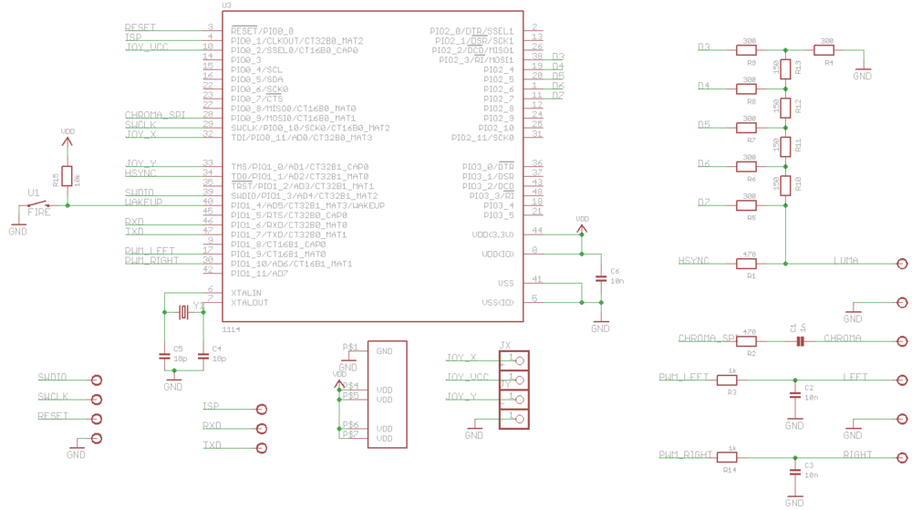
The schematic is virtually identical to the prototype with a few exceptions. The joystick VCC line is connected to a GPIO rather than VCC to reduce power during normal operation and especially during deep power down. The fire button is connected to the WAKEUP pin that brings the beast back from deep power down. The code will deep power down the RBox after 3 minutes of inactivity. While turned off the RBox uses about ~200na as far as I can measure on my crappy meter. The board supports both composite and s-video.
If you don’t feel like making your own pcb order them from http://dorkbotpdx.org/wiki/pcb_order. This is simply the cheapest and best way of getting pcbs in small volume. Nobody else comes close. Unless you really like what ferric chloride does for your sneakers there is no reason not to use these guys.
New code, schematic and pcb posted on https://sourceforge.net/projects/rbox/. If you would like a kit post a comment and if there is lots of interest I will see if I can get one organized.
If you enjoy LCDs and microcontrollers chances are that you have tinkered with the ubiquitous Nokia 6100 screen. I love the fact that a youtube search for “Nokia 6100” produces may more AVR and PIC hacks than phones. In a bit of a departure from my normal projects this is the first in a series of posts on lots of other little known display choices that are better, cheaper and just more fun.
Despite its popularity the Nokia 6100 display has a few problems:
Small (132×132)
It is a CSTN (passive matrix) display leading to ghosting if things move quicky. Koopas are especially lethal if nearly invisible.
Limited color depth of 12 bits (4096 colors + dithering on some displays).
It comes with 2 incompatible driver ics (Philips or Epson).
Not cheap: $15 from sparkfun or (gasp) $35-$42 for breakout boards.
A fiddly, relatively uncommon 0.5mm connector that tends to tear off expensive breakout boards rendering them useless.
Needs 6V for the backlight (2 leds in series).
The Nokia 6100 first shipped in 2002. Of the hundreds of models of phones from nokia (yes, hundreds) surely there are other screens of interest? A quick check in my junk phone archive of hundres of phones (yes, hundreds) turned up a few interesting candidates.
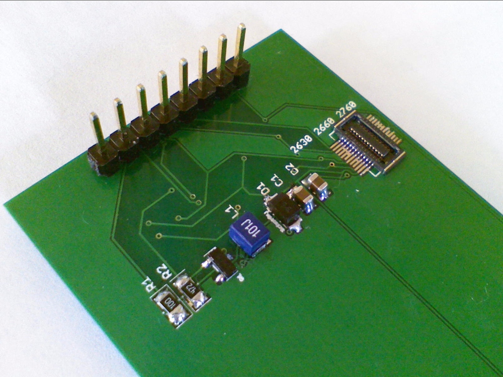
A quick check of the schematics turned up a series of SPI driven displays connected to 10, 22 and 24 sockets.
Nokia 1600: Although the 1600 screen uses the same 10 pin connector (Hirose DF23-10DS) as the Nokia 6100 the pinout is very different – so different in fact that if you plug a 1600 screen into a 6100 phone blue smoke will be emmitted and your phone will become a purely decorative item. The screen is speced as 96×65 CSTN.
Nokia 6101: Two displays here. A 96×65 CSTN caller id screen with backlight leds on the phone pcb (fail/win) and nice big one with a 22 pin 0.5mm connector (Hirose DF23-22DS) that is a 132×162 TFT (acvtive matrix) display.
Nokia 2760: Two displays again: an oh-so-cute teeny 96×65 blue monochrome display with the 10 pin connector and a 132×162 TFT with a 24 pin 0.4mm connector. These are not the Hirose DF30 series; I am still looking for a definitive source.
We know they are SPI, so lets get them wired up to a logic analyser and see if we can identify what controller they use. Once wired up we record the traffic going two and from the LCD as the phone boots. Looking at the traces it is clear that all these phone used a fairly uncommon 3 wire mode of SPI to determine what display is attached.
After an initial 0x11 (Sleep Out) 9 bit SPI command the 0xDA,0xDB and 0xDC (Read Device ID) commands are followed by 8 extra clocks during which the MOSI line is driven by the LCD. In this 3-wire SPI mode the MISO is really SISO (slave in slave out) and is usually not supported by hardware so we will need to bitbang during this discovery phase. This is the way Nokia 6100 phones can tell the difference between the Epson controller (that does not respond to RDDID) and the Philips controller (that does).
Looking at SPI recordings reveal that the controller on the large screen looks an awful lot like the Philips PCF8833 controller in the 6100. Searching by RDDID manufacturer id 38H turns up the Orise SPFD54124B for the 6101 screen. It has a lovely 262k frame buffer and supports a 12,16 or 18 bit color format. Ironically googling this controller led to a great site that details this and other earlier phone displays. The caller id screen seems to be a SED1565 or similar, the 1600 seems similar to the Philips.
The 22 and 24 pin displays support SPI or an 8 bit paralell interface selected by a p/s pin. SPI is usually fast enough for smaller screens unless you are really perf sensitive. SPI means fewer pins on the mcu, fewer lines you need to convert from 5v to 3.3v etc.
Now the really good news. The 6101 displays are really cheap on ebay. <$3 with free shipping much of the time. They address problems 1) thru 5) listed above. The 1600 screens are also cheap if you need something small – dealextreme has them for <$5. 1200 displays are pin and code compatible with the caller id screen an very low power if you don’t use a backlight.
The breakout board above supports both 10pin pinouts as well as 22 0.5mm and 24 0.4mm pinouts. It has a built-in boost converter for generating various led supply voltages controlled by pwm from the mcu. It has a sense pin to allow you to measure the backlight current and adjust it accordingly by varying pwm duty cycle.
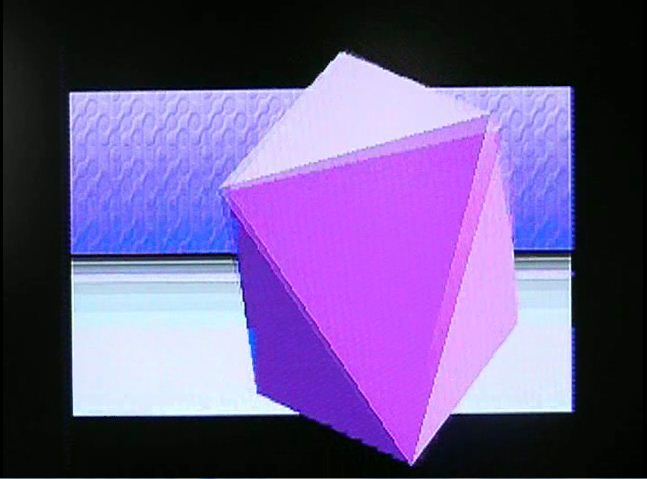
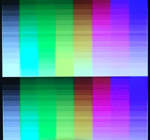
The software in the demo detects when a display is attached, selects the right driver and runs an appropriate graphics app: Wireframe 3D for mono screens, the reference Rossum icosohedron and a raycast lattice for color. As always code and schematics/pcbs will be posted on Sourceforge.
In the next post, I will look at displays from several non-Nokia phones, the worlds cheapest TFT and the Ipod Nano 2G.