Play retro color 8 bit games on your TV from an Arduino.
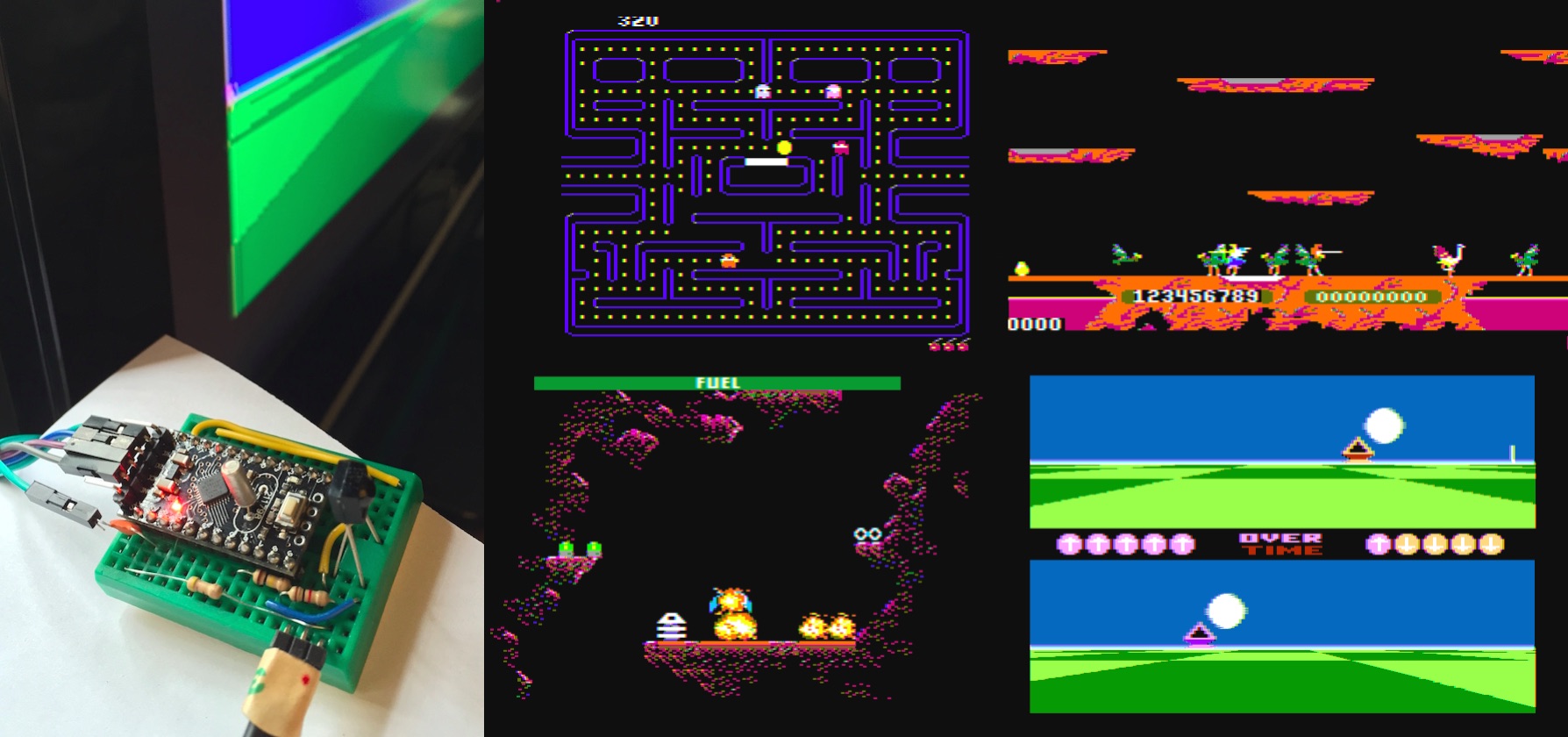
Arduinocade features old school color 8 bit graphics (tiles, sprites, smooth scrolling, simple 3D) and sound (4 voice wavetable synthesis). All video and audio signals are generated with three resistors, an upgraded crystal and a little software. By overclocking the Arduino to 28.6363Mhz we can directly manipulate NTSC to generate 27 simultaneous colors. An IR receiver supports a wide variety of keyboards, joysticks and remote controls.
Video of Arduinocade in action at https://www.youtube.com/watch?v=nGIujZiEu_o
Code, tools, schematics and more detail at https://github.com/rossumur/Arduinocade
Games
These games are sketches of what is possible on the Arduinocade hardware and a far from the polished pieces that inspired them.
Ballblaster
A one-on-one sports style game inspired by the brilliant 1984 game Ballblazer. This uses a simple physics model and a 2D/3D rendering pipeline to produce 60fps animation. Try and grab the ball and shoot it into your opponent’s goal.
Pacman
What can I say? pakku pakku pakku.
Jowst
Fly around on ostrich thingys. Poke each other with sticks. Nice example of using the sprite engine to generate lots of large multicolor sprites.
Caverns of Titan
Homage to the Atari classic “Caverns of Mars”. Smooth scrolling, sprites and animation.
Building the Hardware
Lots of different ways to build this beastie. The design is simple enough to build on a breadboard with a DIP Atmega328, alternatively you might want to add a 28.6363Mhz crystal to a $2 Arduino Pro Mini or even build on a custom PCB.
You will need
- Arduino Pro Mini, Atmega328p or equivalent
- 28.6363Mhz Crystal (from Adafruit, eBay etc)
- RCA Audio/Video Cable (eBay)
- 470ohm, 1k and 100k resistors
- IR receiver TSOP38238,TSOP4838 or equivalent (Adafruit, Mouser etc)
- IR Input device (see below)
        +----------------+
        |    arduino     |
        |    uno/pro     |
        |     28Mhz      |       5v <--+-+   IR Receiver
        |                |      GND <--|  )  TSOP4838
        |              8 |-------------+-+
        |                |
        |              6 |----[ 100k ]--------> AUDIO
        |                |
        |              9 |----[  1k  ]----+---> VIDEO
        |                |                |
        |              1 |----[ 470  ]----+
        |                |
        |              3 |
        |              2 |
        |                |
        +----------------+
Mini Pro
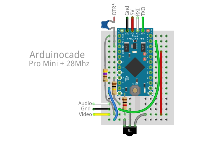
We will be upgrading the crystal/resonator on these boards from 16Mhz to 28.6363Mhz. The easiest ones to modify have the big silver cans on them. Others use a ceramic resonator which require a bit of SMD fiddling.
Custom PCB
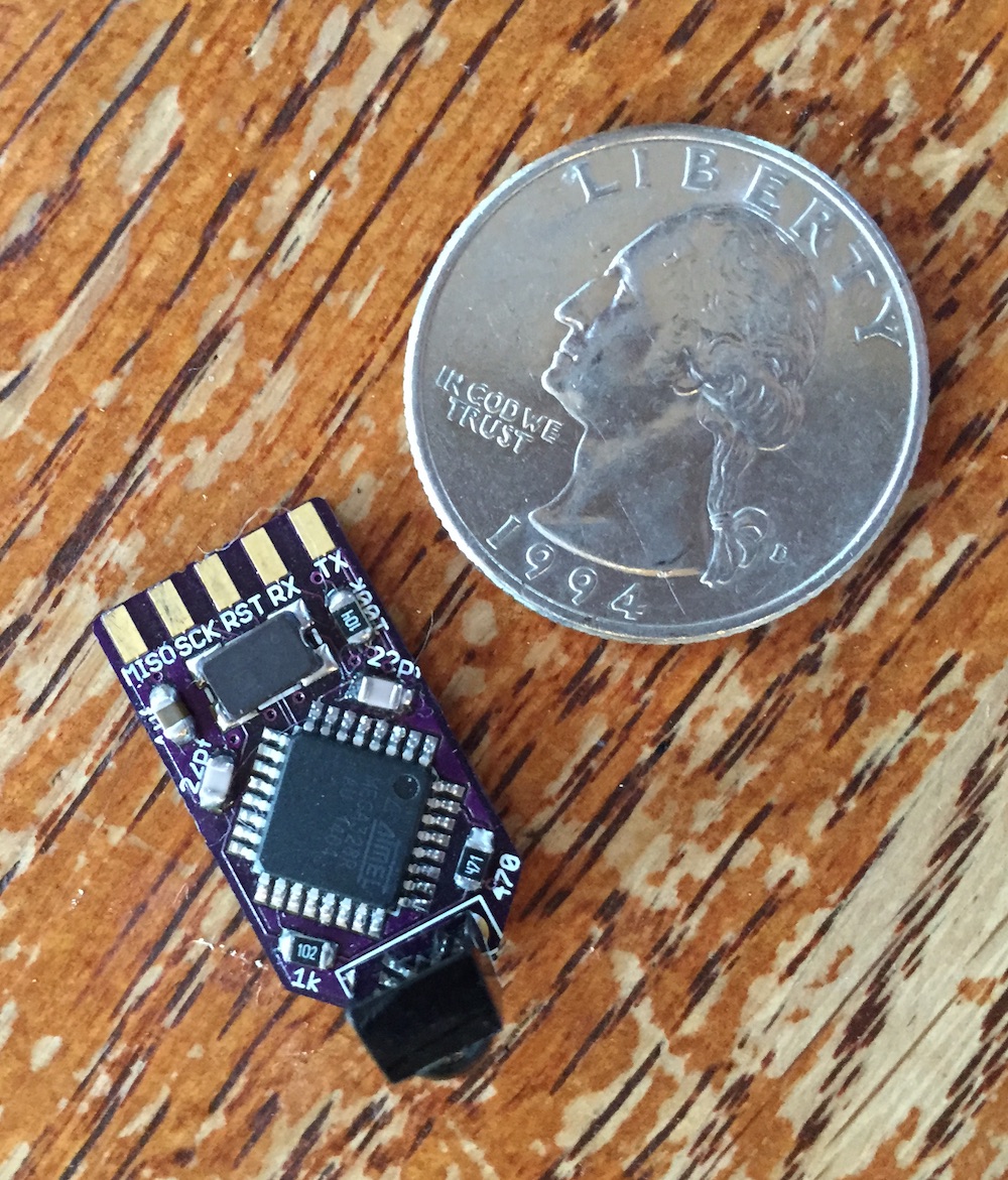
If you want to get silly and build a custom board you can get a video console down to about the size of a quarter. Board and schematics can be found in sim/docs/eagle.
Input Devices
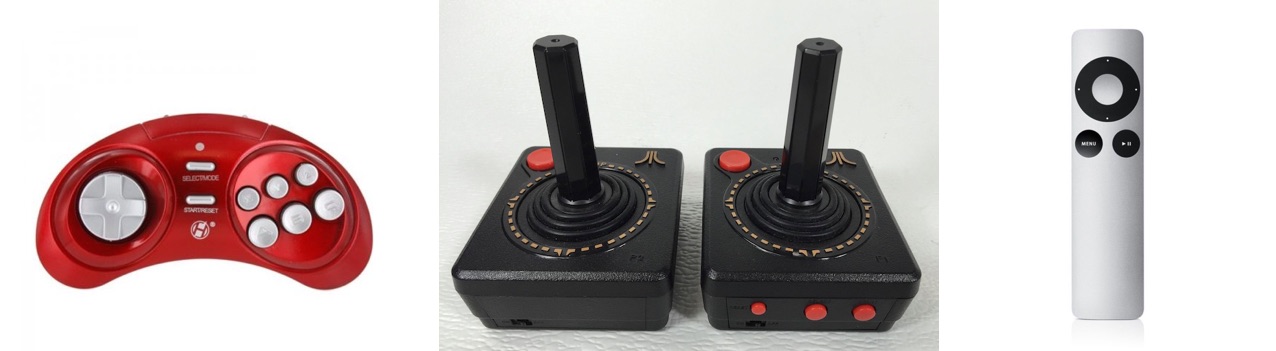
Retcon IR Controller, Atari Flashback 4 joysticks, Apple TV remote
A number of IR input devices are supported. The IR Wireless Controllers from Atari Flashback 4 work well and have that classic joystick feel, as do the Retron IR controllers. These can be readily found on eBay for a few bucks. The Apple TV remote is also supported by you might feel a little silly. Edit config.h to select your input of choice.
Upgrading the bootloader
If you want to use the Arduino IDE you should upgrade the bootloader to be able to work at 115200 baud with the faster crystal installed. The optiboot_atmega32_28.hex image has been rebuilt with F_CPU=28636363 and a slower watchdog reset so baud rate calculations will be correct for our overclocked device. Install the image with avrdude and your favorite ISP.
avrdude -c usbtiny -p atmega328p -e -u -U lock:w:0x3f:m -U efuse:w:0x05:m -U hfuse:w:0xDE:m -U lfuse:w:0xFF:m
avrdude -c usbtiny -p atmega328p -U flash:w:optiboot_atmega328_28Mhz.hex -U lock:w:0x0f:m
Once the modified optiboot is installed the device will behave like an Uno, so remember to select that from the boards menu in the Arduino IDE.
Using the Arduino IDE
Note:
The current code does not work correctly with Arduino IDEs later than 1.5.6. Compiler optimizations in later versions interfere with hand timed loops in the video kernels. I will fix soon.
Copy the `Arduinocade` folder into the IDE libraries folder and relaunch IDE. You should be able to open the example games from File->Examples->Arduinocade. Edit the config.h file to enable or disable the custom `BALLBLASTER_GAME` kernel.
How it works
Video
Upgrading the crystal to 28.6363Mhz allows us to run at a multiple (8x CPU clock, 4x SPI output) of the NTSC subcarrier frequency. By spitting out bits in the right pattern at the right time we can generate NTSC colorburst and different colors based on the relative phase of the pattern.
Black (0000), White (1111), gray_5 (0101) and gray_10 (1010) don’t have a chroma component; the other 12 colors do. By inserting or skipping an extra nop in rendering kernel we can select between two different phases at the start of a line yielding 12+12+(black,white,gray) = 27 simultaneous colors on screen simultaneously. You can then add more by dithering etc.
The Art of Artifacts
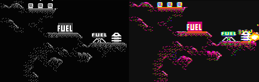
Left – Pixels being emitted from the TX port, Right – Colors as they appear on NTSC
Every HSYNC interrupt the cpu emits a 3.57Mhz colorburst signal then sends pixel data from carefully timed tile or RLE video kernels. These are tricky to maintain in C, as helpful compiler optimizations often alter timing in unexpected ways. They probably all need to move to asm at some point. See note above.
The higher layer code uses a RLE format (BallBlaster) or tiles to represent game content. Because we don’t have enough memory for a full frame buffer individual lines of tiles and sprites are composed in a loop that is in lock step with the HSYNC interrupt.
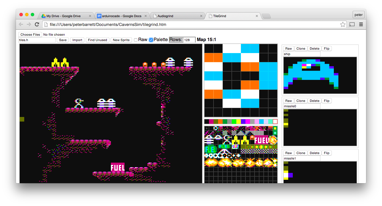
TileGrind is a primitive html/javascript tool for generating color tiles and sprites. It can load and save C structs and understands the nature of NTSC color phase / artifacting. Its limitations vividly recreate the frustration of early graphics editing tools.
Audio
The Audio driver has two parts. The low level kernel runs every HSYNC, stepping each of the 4 voices though it’s wavetable, mixing the sampled voices together based on their current volume and emitting a sample to the PWM/resistor single bit DAC. This corresponds to a sample rate of 15734Hz.
The high level task runs every frame at 60Hz and adjusts envelope, modulates frequency of the underlying channels etc. It is responsible for parsing data structures containing music tracks and sound effects, adjusting volume envelopes and frequencies, swapping wavetables for different instruments etc.
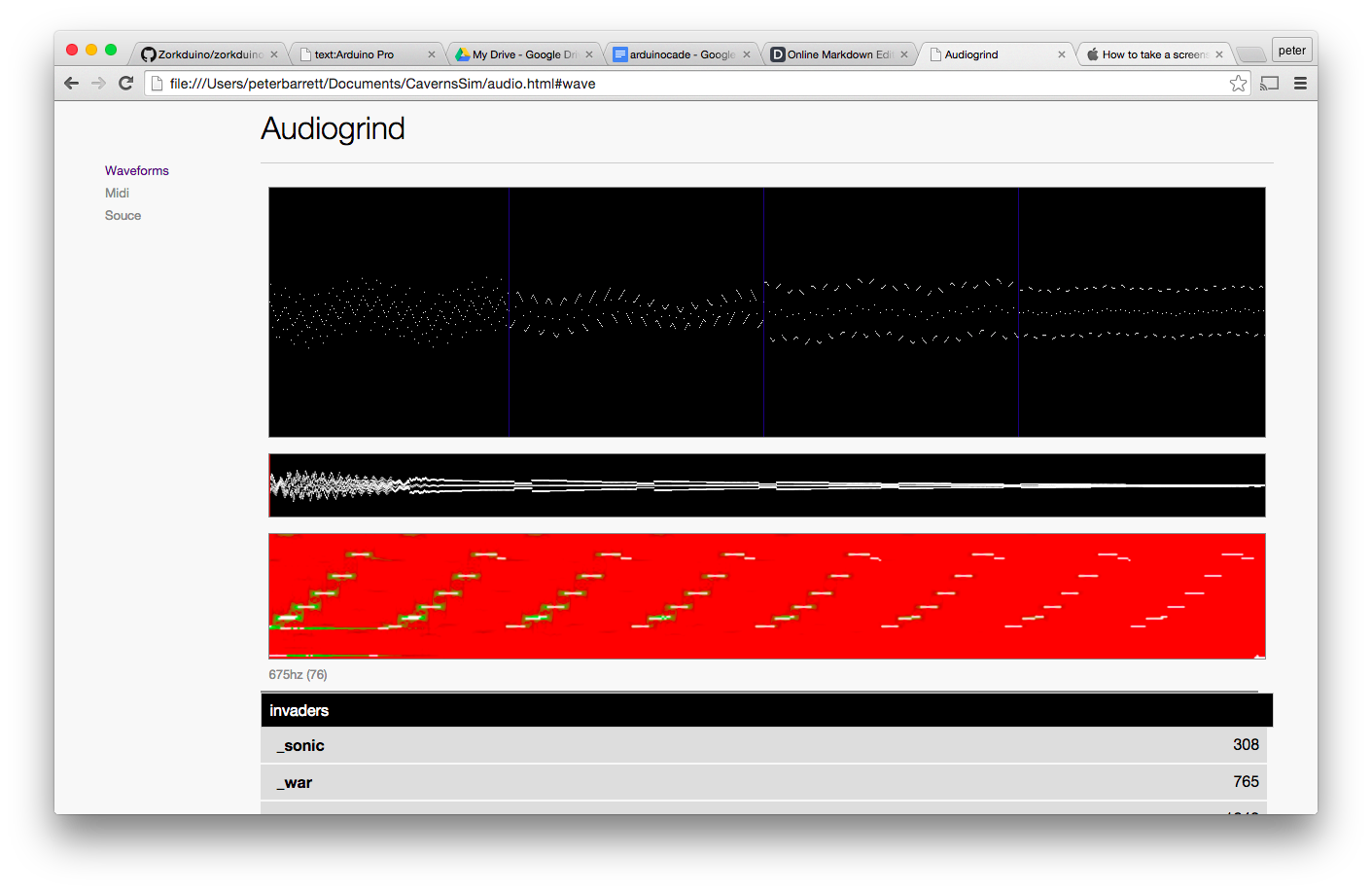
AudioGrind is a primitive html/javascript audio editing tool is used to convert midi files to C struct data. It can also be used to reverse engineer classic gaming sound effects using a graphical spectrogram, without which it is nearly impossible to figure out how the effects are constructed – I’m talking to you Joust.
IR input Joysticks, Keyboards etc
The GPIO attached to the IR sensor is sampled at HSYNC and fed to one of a number of IR decoders. The 15734Hz sample rate is enough to accurately parse nearly all IR protocols. For performance reasons only one is enabled at a time; check the #ifdefs in ir_input.cpp.
So enjoy
Let me know if you have some fun with it.
Cheers,
Rossum

Rossum, you are my hero!
It can’t be more minimal than that.
As I live in Europe, do you know if the NTSC trick can be transposed to PAL?
Yes, although there are a few differences. The video pipe needs to be tweaked to alternate the phase every line and the crystal needs to match 8x the PAL subcarrier. The tricky bit is that 35.468Mhz is right at the top end of what you can get out of overclocking, so you will probably need to run at > 5V to make it reliable. 4x AA batteries work well here.
I grew up in a PAL country and have a deep affection for it. I have a monitor on the way so if I find a free weekend I will have a crack at it.
cheers
This is brilliant, I’m wondering if this is something that could be designed to be put onto a USB stick, so powered via the TV in a very small unit?
USB is a great power source on TVs. The custom PCB is really small and would fit in a USB “A” connector but because it carries the IR receiver I elected to have the USB plug (and the AV plugs) attached by cables.
This is so much more l33t than I could ever imagine to be. Legacy. Punches sky.
Amazing, well done mate!
I am also using PAL TVs (from UK 😀 ), would there need to be any changes to the NTSC code for it to work on pal after swapping the crystal oscillator to 35.468 MHz and upping the input voltage to 6v?
Also how would it be best to program with the new crystal frequency on a standalone atmel 328p ic as apposed to an arduino board.
Sorry to bombard you with questions.
Thanks, Joe
PAL is tricky because of the line-to-line alternating phase. That means that tilesets (and sprites etc) need to alternate phases/positions every line as well. Not a show stopper but a head scratcher.
A new crystal frequency just needs an adjustment of the UART scaling factors in the bootloader, easy to do with the standard 6-pin SPI AVRISP programming method.
How would I go about changing the bootloader, would it be done without using the arduino software?
And where would I get the bootloader from.
Sorry for all the questions, I’m pretty much a noob with programming 🙂
You will need another Arduino or a AVRISP to reflash the bootloader. https://www.arduino.cc/en/Tutorial/ArduinoToBreadboard
Cool, yeah I’ve got an uno and blank 328p ic’s. I see I the code/files you’ve posted there’s a hex file for the NTSC version. I don’t suppose you have a hex for the PAL at 35.468 MHz?
Many thanks, Joe 🙂
Does the arduino IDE have the bootloader built in to overclock to 35MHz. If not where can I obtain it?
Thank you for your help 🙂
Very Cool! Have you tried 28.636MHz on more than a couple ‘328s? (Just curious– I always had about 10-15% fallout on the Mega644 clocking it at 28.636MHz when I did the AVCore boards for the Uzebox.)
I have tried about a dozen and have had no problems so far. It might be that 328ps tend to be a later process or that less RAM makes them less vulnerable.
Ahh, yes, that could be– when I tried Mega1284’s I had 100% fallout @ 28.636, so that might follow the pattern. Incidentally, did your Atari microSD project tree ever make it online? (I didn’t see it on GitHub last I looked.)
(sorry if double post, appears my earlier one didn’t go)
I had 100% failures trying to get the Mega1284 to run @28.636MHz, so that might fit the pattern WRT RAM or Flash size. (Since the 1284 was a later process than the 644 as well.)
Sorry to threadjack, but did your project tree for the Atari microSD drive ever make it online? (I couldn’t find it, but realized that it was back in the .posterous days when I first looked.)
Would I need to use a different hex file for the new bootloader or could I use the same one for NTSC but for PAL? If it needs to be different could do you have a file ready so as I could try this on PAL?
It works!

Could you add the option of standard joystick (wired buttons)?
That is awesome. I love the A/V interface with the dust of storied history!
It should be easy to add a wired controller; DB-9 for old ataris and c64. I promise I will add it on a free weekend.
cheers
+1
Could you add the option of standard joystick (wired buttons)?
Sorry for the double post, please delete.
Rossum, you are in smart individual. Amazing. As an engineer, I have seen many people at work who are 1/2 smart of you but act like they know everything. You should seriously think about be your own boss and have your own company, since you definitely have potentials! Don’t waste your time working for other people like I have been 🙂
Question on studying the code, the video.cpp file:
// Color clock frequency is 315/88. How is this calculated? Where do the “315” and the “88” come from?
// CPU Mhz is 315/11. How is this calculated? Where does the the “11” come from?
I commented the below, so that others can understand better.
// ~1820 cpu clocks per line at 28.6363Mhz
// Timing: https://www.maximintegrated.com/en/images/appnotes/734/DI39Fig05.gif
// Color: http://www.extron.com/company/article.aspx?id=ntscdb1d
// Color & voltages: http://www.tri-sysdesigns.com/Articles/BlackisBlack.html
#define USEC(_x) (((_x)*28.6363)-1)
#define TICKS_SCANLINE (1824-1) // Entire number of ticks per scan line at 28.6363Mhz.
#define TICKS_HSYNC USEC(4.7) // 4.7usec of 0V as the HSYNC AFTER the 1.5usec front porch.
#define TICKS_LONG_HSYNC USEC(63.555-4.7) // basically the time to do video data blitting!
#define TICKS_HBLANK USEC((4.7+1.5)) // The time the electron beam moves from left to right for the next scan line.
#define TICKS_INTERRUPT USEC(4.05) // late as possible 4.2
#define TEXT_ROWS 24 // 24 rows per screen.
#define TEXT_COLS 40 // 40 columns per screen.
#define BLANK_LINES 40 // Vertical retrace time to do work! 63.555usec * 40
#define ACTIVE_LINES (TEXT_ROWS*8) // 192 active scan lines.
315/88 == NTSC color clock at 3.579545. CPU is 8X color clock or 315/11 == 28.6363Mhz
Nice detail on rationale at https://en.wikipedia.org/wiki/Colorburst.
In video.cpp, there are the below externs, which are not defined anywhere. Do they mean to be “externs”?
extern volatile uint8_t* _read_rle;
extern uint8_t _bb_buf[BUFFER_SIZE + MAX_LINE_BYTES];
These reference the run length buffers used by the Ballblaster game.
Pingback: Consola de Vídeo Juegos de 8 bits con Arduino
On some 7″ Lcd displays the screen image is rolling. Seems like the vsync is out of sync.
I thank Rossum for the arduinocade project. I am making several modifications from its original source code.
By increasing the voltage to 5.2v of the board, it can be executed perfectly in an arduino one clone.
I have modified the PACMAN code to be able to use a gamepad with simple ground buttons (ATARI JOYSTICK).
I have modified the javascript tool to load a 4×8 tile and a large sprite in several TILES. It is a proof of concept, it is not yet suitable for the end user.
https://github.com/rpsubc8/ArduinoVideoConsole
Just saw this. Really cool. Tilesets are fantastic, love the wired joystick support.
congrats