Play retro color 8 bit games on your TV from an Arduino.
Arduinocade features old school color 8 bit graphics (tiles, sprites, smooth scrolling, simple 3D) and sound (4 voice wavetable synthesis). All video and audio signals are generated with three resistors, an upgraded crystal and a little software. By overclocking the Arduino to 28.6363Mhz we can directly manipulate NTSC to generate 27 simultaneous colors. An IR receiver supports a wide variety of keyboards, joysticks and remote controls.
Video of Arduinocade in action at https://www.youtube.com/watch?v=nGIujZiEu_o
Code, tools, schematics and more detail at https://github.com/rossumur/Arduinocade
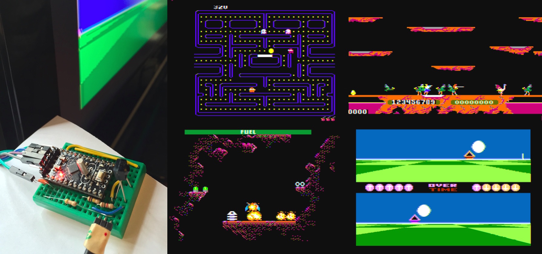
Games
These games are sketches of what is possible on the Arduinocade hardware and a far from the polished pieces that inspired them.
Ballblaster
A one-on-one sports style game inspired by the brilliant 1984 game Ballblazer. This uses a simple physics model and a 2D/3D rendering pipeline to produce 60fps animation. Try and grab the ball and shoot it into your opponent’s goal.
Pacman
What can I say? pakku pakku pakku.
Jowst
Fly around on ostrich thingys. Poke each other with sticks. Nice example of using the sprite engine to generate lots of large multicolor sprites.
Caverns of Titan
Homage to the Atari classic “Caverns of Mars”. Smooth scrolling, sprites and animation.
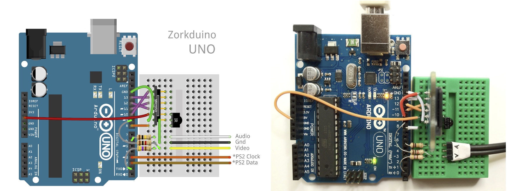
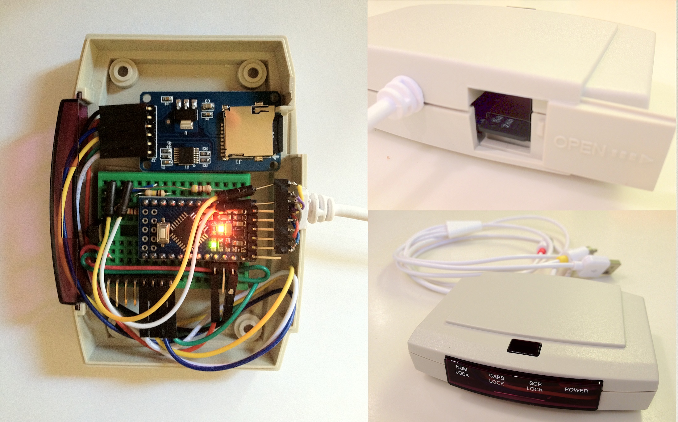
Building the Hardware
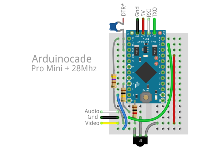
Lots of different ways to build this beastie. The design is simple enough to build on a breadboard with a DIP Atmega328, alternatively you might want to add a 28.6363Mhz crystal to a $2 Arduino Pro Mini or even build on a custom PCB.
You will need
- Arduino Pro Mini, Atmega328p or equivalent
- 28.6363Mhz Crystal (from Adafruit, eBay etc)
- RCA Audio/Video Cable (eBay)
- 470ohm, 1k and 100k resistors
- IR receiver TSOP38238,TSOP4838 or equivalent (Adafruit, Mouser etc)
- IR Input device (see below)
        +----------------+
        |    arduino     |
        |    uno/pro     |
        |     28Mhz      |       5v <--+-+   IR Receiver
        |                |      GND <--|  )  TSOP4838
        |              8 |-------------+-+
        |                |
        |              6 |----[ 100k ]--------> AUDIO
        |                |
        |              9 |----[  1k  ]----+---> VIDEO
        |                |                |
        |              1 |----[ 470  ]----+
        |                |
        |              3 |
        |              2 |
        |                |
        +----------------+
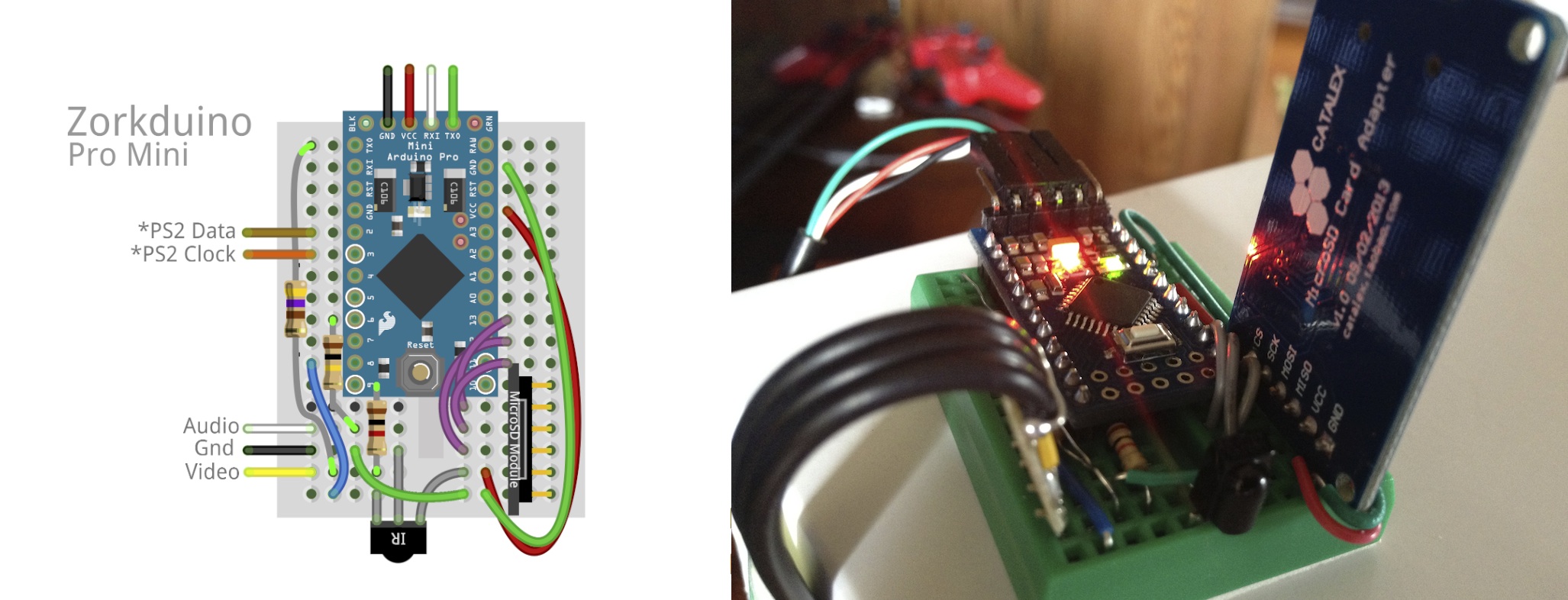
Mini Pro
We will be upgrading the crystal/resonator on these boards from 16Mhz to 28.6363Mhz. The easiest ones to modify have the big silver cans on them. Others use a ceramic resonator which require a bit of SMD fiddling.
Custom PCB
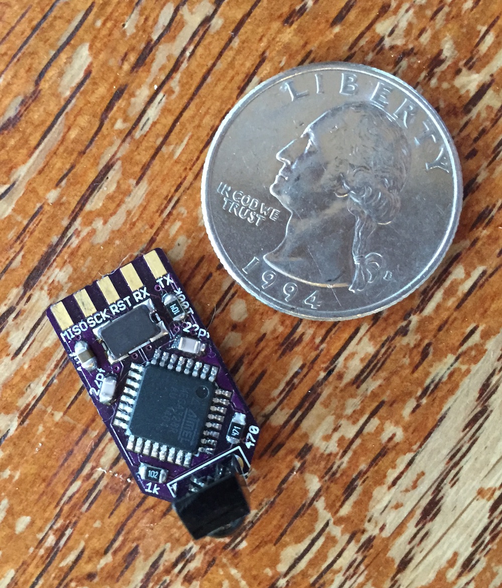
If you want to get silly and build a custom board you can get a video console down to about the size of a quarter. Board and schematics can be found in sim/docs/eagle.
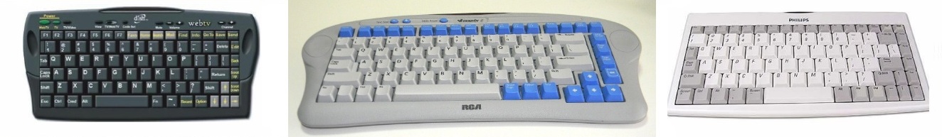
Input Devices
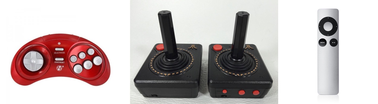
Retcon IR Controller, Atari Flashback 4 joysticks, Apple TV remote
A number of IR input devices are supported. The IR Wireless Controllers from Atari Flashback 4 work well and have that classic joystick feel, as do the Retron IR controllers. These can be readily found on eBay for a few bucks. The Apple TV remote is also supported by you might feel a little silly. Edit config.h to select your input of choice.
Upgrading the bootloader
If you want to use the Arduino IDE you should upgrade the bootloader to be able to work at 115200 baud with the faster crystal installed. The optiboot_atmega32_28.hex image has been rebuilt with F_CPU=28636363 and a slower watchdog reset so baud rate calculations will be correct for our overclocked device. Install the image with avrdude and your favorite ISP.
avrdude -c usbtiny -p atmega328p -e -u -U lock:w:0x3f:m -U efuse:w:0x05:m -U hfuse:w:0xDE:m -U lfuse:w:0xFF:m
avrdude -c usbtiny -p atmega328p -U flash:w:optiboot_atmega328_28Mhz.hex -U lock:w:0x0f:m
Once the modified optiboot is installed the device will behave like an Uno, so remember to select that from the boards menu in the Arduino IDE.
Using the Arduino IDE
Note:
The current code does not work correctly with Arduino IDEs later than 1.5.6. Compiler optimizations in later versions interfere with hand timed loops in the video kernels. I will fix soon.
Copy the `Arduinocade` folder into the IDE libraries folder and relaunch IDE. You should be able to open the example games from File->Examples->Arduinocade. Edit the config.h file to enable or disable the custom `BALLBLASTER_GAME` kernel.
How it works
Video
Upgrading the crystal to 28.6363Mhz allows us to run at a multiple (8x CPU clock, 4x SPI output) of the NTSC subcarrier frequency. By spitting out bits in the right pattern at the right time we can generate NTSC colorburst and different colors based on the relative phase of the pattern.
Black (0000), White (1111), gray_5 (0101) and gray_10 (1010) don’t have a chroma component; the other 12 colors do. By inserting or skipping an extra nop in rendering kernel we can select between two different phases at the start of a line yielding 12+12+(black,white,gray) = 27 simultaneous colors on screen simultaneously. You can then add more by dithering etc.
The Art of Artifacts
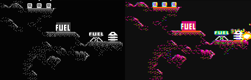
Left – Pixels being emitted from the TX port, Right – Colors as they appear on NTSC
Every HSYNC interrupt the cpu emits a 3.57Mhz colorburst signal then sends pixel data from carefully timed tile or RLE video kernels. These are tricky to maintain in C, as helpful compiler optimizations often alter timing in unexpected ways. They probably all need to move to asm at some point. See note above.
The higher layer code uses a RLE format (BallBlaster) or tiles to represent game content. Because we don’t have enough memory for a full frame buffer individual lines of tiles and sprites are composed in a loop that is in lock step with the HSYNC interrupt.
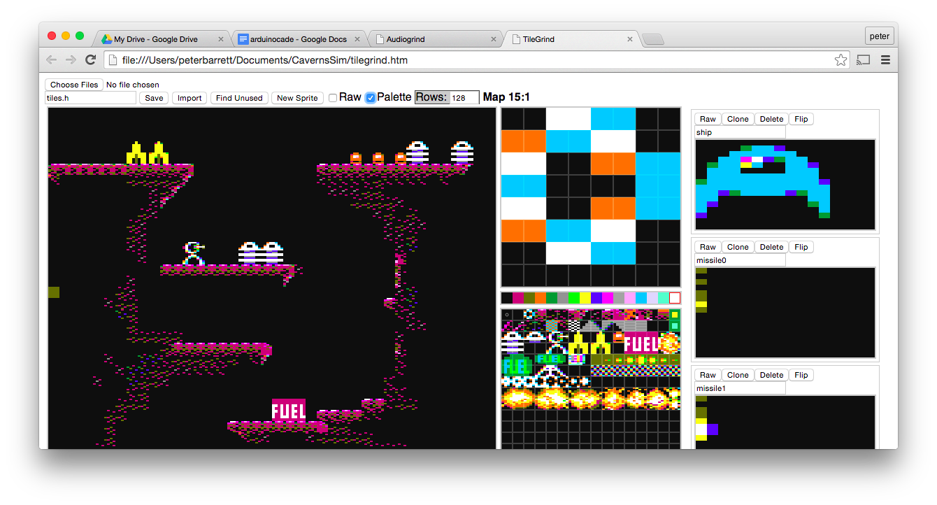
TileGrind is a primitive html/javascript tool for generating color tiles and sprites. It can load and save C structs and understands the nature of NTSC color phase / artifacting. Its limitations vividly recreate the frustration of early graphics editing tools.
Audio
The Audio driver has two parts. The low level kernel runs every HSYNC, stepping each of the 4 voices though it’s wavetable, mixing the sampled voices together based on their current volume and emitting a sample to the PWM/resistor single bit DAC. This corresponds to a sample rate of 15734Hz.
The high level task runs every frame at 60Hz and adjusts envelope, modulates frequency of the underlying channels etc. It is responsible for parsing data structures containing music tracks and sound effects, adjusting volume envelopes and frequencies, swapping wavetables for different instruments etc.
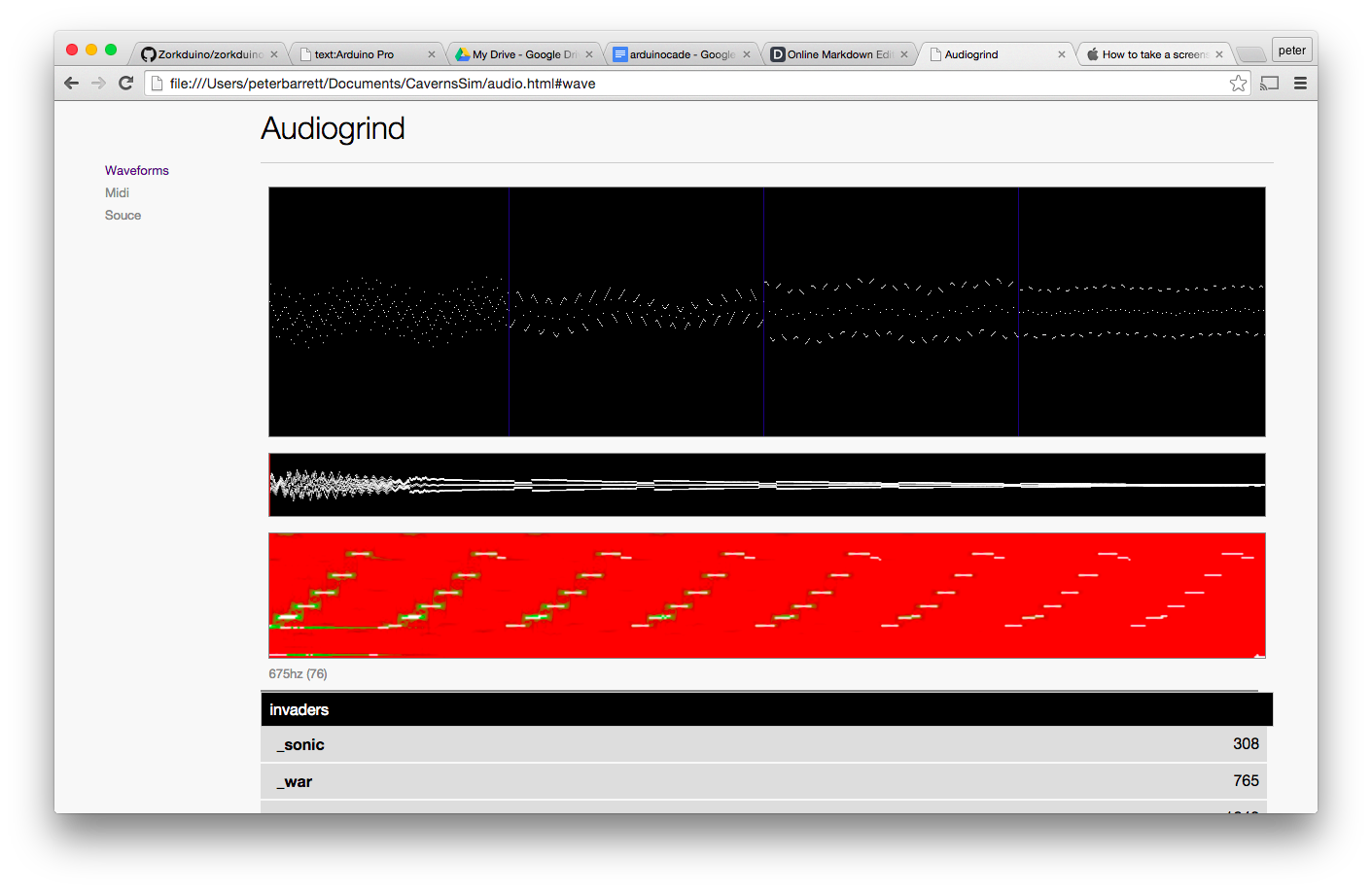
AudioGrind is a primitive html/javascript audio editing tool is used to convert midi files to C struct data. It can also be used to reverse engineer classic gaming sound effects using a graphical spectrogram, without which it is nearly impossible to figure out how the effects are constructed – I’m talking to you Joust.
IR input Joysticks, Keyboards etc
The GPIO attached to the IR sensor is sampled at HSYNC and fed to one of a number of IR decoders. The 15734Hz sample rate is enough to accurately parse nearly all IR protocols. For performance reasons only one is enabled at a time; check the #ifdefs in ir_input.cpp.
So enjoy
Let me know if you have some fun with it.
Cheers,
Rossum