Gotta love Wikipedia. Gotta love really cheap, powerful Microcontrollers. They are even more delightful when combined.
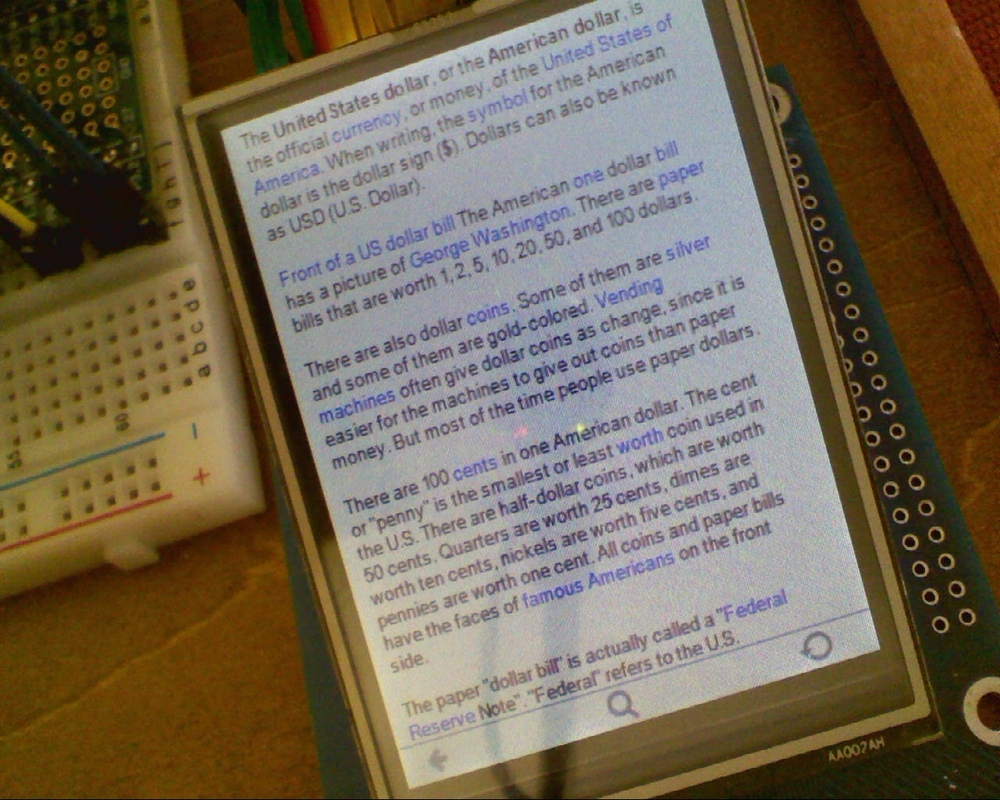
This is a prototype of a cheap offline wikipedia reader based on a new NXP ARM Cortex M0 microcontroller. It renders offline dumps of Wikipedia or other text formats (books, html etc) with a simple touch interface. The dumps are stored on a microSD card and are rendered on a inexpensive touchscreen LCD. I will publish full schematics, PCB layout and source code to a final handheld version that looks an awful lot like the Microtouch.
The Software
An offline grinder tool converts xml dumps from wikipedia and other sources into a compressed text layout format that is digestible on a small device. The hard part is decompressing and drawing the text with few cycles and very little RAM fast enough for it to feel like a responsive little consumer electronics device rather than a lumbering PC. The keys to this turned out to be a spatial index that allowed fast rendering of segments of a page and hugely simplified compression. The text renderer uses subpixel positioning to help make teeny fonts readable without slowing down drawing.
The Hardware
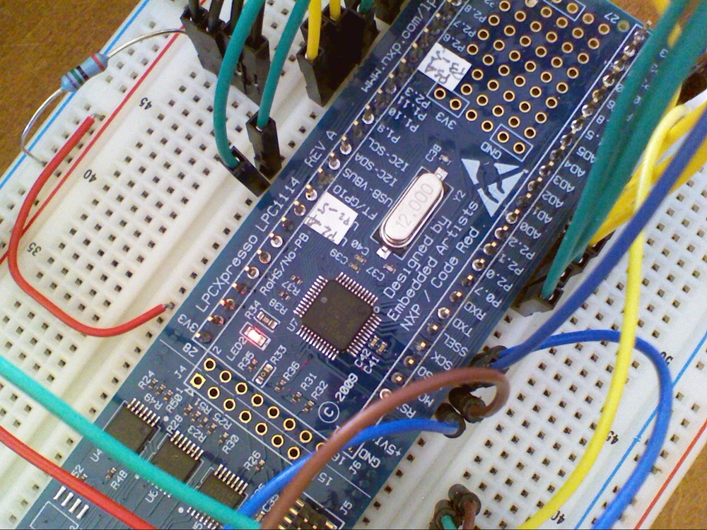
NXP are onto something good with these ARM Cortex microcontrollers. The are cheap in onesies (<$2), fast (50Mhz), have plenty of memory (32K flash, 8K sram) and have a really nice dev kit (LPCXpresso) with Eclipse based tools and delightful Serial Wire Debug. Hardware breakpoints. 12K gates. Bloody amazing.
This project uses the LPC1114 Cortex M0 but the PCB will also take a LPC13XX Cortex M3 part that is faster (72Mhz) and has full speed usb. The prototype uses a LPCXpresso kit with lots ‘o jumpers and a ILI9325 based LCD, the same as the Microtouch.
What about the AVR?
As it turns out, this also runs just fine on the AVR based Microtouch classic hardware. It isn’t quite as zippy but still works well. The code isn’t really optimized yet and there is probably room for improvement on both platfotms. You might expect the Cortex M0 version running at 48Mhz to be 4 times as fast. It isn’t. The M0 always requires 2 clocks to read or write GPIO (unlike a single clock for the AVR) so the LCD blit loops are at best twice as fast. Code size is about the same as one might expect.
For those of you who have built your own Microtouch device I will make sure the classic hardware is fully supported. For those of you who have not built their own Microtouch yet I hear that there might be a kit in the works. Watch this space.
Until next time,

Update
Code and schematics posted at http://www.lpc1100challenge.com/detail/316

Oh, huzzah. I’ve noticed that my Ipad is almost always just a very, very expensive Wikipedia reader. And until Wikipedia articles all have the richness of Theo. Gray’s elements e-book, it’s a waste.
Thank you, sir, for this bit of brilliance.
Very impressive Sir. I (as I am sure many are) am curious as to your hardware sources, especially LCDs. I would very much enjoy having an inexpensive source of LCD modules to work with. Occasionally one can find a good deal on ebay, but those seem to be fleeting and have a tendency to disappear without notice.
Looks great! +1 about the LCDs, I’d love to find a cheap source of sensibly sized LCDs that contain a controller with RAM
You’ve done it once again. This is exactly what a friend and I were looking for. We were going to start from your Microtouch design and work up to this. Cant wait to get started on it. Brilliant.
Brilliant! I (like many, I’m sure) have been tossing around the idea of a DIY wikipedia-box for a while, and your implementation looks fantastic. Would love to make one as soon as schematics and code are available. Unless… would you like to partake in a bit of barter? (hypnocube.com – I’d be happy to trade, say, a finished 4Cube. If interested, please hit up the contact on the site. Thanks!)
What software are you using?
For those of you wondering you can make this exact setup for around $75 using these sources:
LCD’s goto ebay store “E’go China Electronics” specifically id #200424248713 for this exact touch screen (not sure about the touch controller but their all pretty much the same) $39
For the ARM Cortex-M0/3 goto mouser.com or digi-key.com and search for LPCXpresso they have the LPC1114 and LPC1343 for $32
Any idea when your going to make the source available Rossum?
Do any one have data sheet of #200424248713 from E’go China Electronics” ?
Excellent source microminded, thanks!
Rossum mentioned in the microtouch comments that he got the LCD from a cheap MP3 player that can be easily found on ebay or chinese electronics stores. Only one particular model uses the two controllers he supports, but can be had for $5-40.. depending on how lucky you are.
As for sources of LCDs I found over the past few years: ThaiEasyElec makes an 8-bit parallel (much slower, from my experience) breakout board version of the ILI9325 controller LCD for ~$60. They have a 8/16-bit Arduino-shield compatible SSD1289 $60 board as well w/ a plethora of bells and whistles but it’s been out of stock for nearly half a year. Embedded Artists makes a SSD1289 OLED version for 150 smackers (great board – 8-bit, 16-bit and SPI but extremely expensive). TechToys makes a number of LCD/controller breakout boards for a good price, though most of their smaller boards are being discontinued or out of stock… They mostly focus on 3.5-7″ stuff now from the looks of it.
From just the looks of the blue PCB on that LCD’s breakout board, it seems like something EA would produce.. though their LCD modules look nothing like that.
Rossum, you continue to surprise us – keep it up!
Would the Cortex M0 be comparable to any AVR (XMega or AVR32)? I’ve got the ($60, completely overpriced online-compiler-based PoS) mbed unit that has a 100MHz Cortex-M3.. and I find it ungodly slow. It takes nearly 10 times longer to complete a LCD demo than my 32MHz XMega128A1, though that may be due to the fact mbed’s APIs aren’t very fast for I/O access… plus the code may not have been completely optimized.
On a side note, I still can’t figure out how you yield such high performance out of those little AVRs. I’ve got a 32MHz XMega running nearly the same ILI9325 library you use for an 8-bit parallel screen (physical limitation of the ThaiEasyElec board, until I get that raw LCD hooked up) and I can’t do anywhere near as smooth blitting from PROGMEM or SD as you (30-700 thousand pixels per second max w/ logic – 1Million Pixels/s if just demo). I can do BRILLIANT 60FPS+++ update animation to a small 6k pixel area of the LCD via double-buffering, but in order to do a full frame double buffer I’d need to sacrifice 4-ports for a 512kB external SRAM chip and even accessing the SRAM would cut down majorly on my LCD write performance.
-robodude666
Tumma – You can download his schematics, datasheets,and examples from the ebay page. Theirs a ‘download’ link by the board picture.
This is so fucking awesome… How large is the max. supported microSD?
This is really damn cool. I wish I understood half of what you guys are talking about. I wouldn’t even know where to start on a project like this
Damn nice work Rossum! Congrats on a job well done.
If anyone here is from the UK and wants next-day delivery on a LCD module similar to this one using the same LCD and Driver check out this site. I just purchased one and it arrived today. I am going to attempt to make something similar. http://www.skpang.co.uk/catalog/product_info.php?products_id=610
To netcore2k, and anyone else who gets/uses that particular LCD, be warned that it is physically limited to only 8-bit. The performance you can yield out if it is about 2-3x lower than what you can actually do with the 16-bit interface that Rossum is using. I’ve been using that exact LCD for a few months and have noticed these limitations.
To help with the LCD sales here is another place you can get the modules from. Same controller and touch ic but just as Robodude666 said its 8bit only on the pcb. They have the Displays for $30 without level shifting or a touch ic if you want that extra speed.
http://www.thaieasyelec.net/index.php//Display-Module/TFT-with-TP/2-8-inch-QVGA-TFT-LCD-with-Touch-Screen/p_8.html
http://www.thaieasyelec.net/index.php//Display-Module/Breakout-Board/Breakout-Board-2-8-inch-QVGA-TFT-LCD-with-Touch-Screen/p_3.html
And Rossum sure doesn’t seem to be that active here… Hopefully he posts his project files soon I’m dieing to see how he made the interface and is displaying the wiki xml dumps!
Brilliantly done, as usual. There are few people I am in awe of, but you are one of them. LPCExpresso sounds brilliant — gotta get off my arse and get me some of that.
My LPCExpresso arrived today and a LiPoly 1000mAh battery so I can hopefully make something semi-portable. @robodude666: Thanks for the tip. I will eventually get one of the same modules from “E’go China Electronics”. First I need to get the LPC1114 working with the ILI9328. I will post pics when I can.
If you guys want I can send you a mp3 player that has a nice screen, lipo and other useful giblets. Gratis if you promise to make something.
You could also send mail to adafruit and say you would like them to stock the screen.
BTW the Wikipedia Cortex PCB supports both the LPC1114 and the LPC1343 (72mHz, single cycle write, flash accelerator, USB) so you might want to be fiddling with the 1343 version of the LPCXpresso too.
Hey, thanks for all your work Rossum you have inspired quite a following!
I would love to take the mp3 player but I’m just getting out of school and monies tight so I would not be able to make something for quite some time. I also wish to buy a LPCXpresso 1343 soon as I have never worked with an ARM before but they seem to own the consumer embedded market. I didn’t notice in the datasheets that the 1343 has single cycle port writes though, I will defiantly be getting the 1243 then.
Any idea when you gonna release the code? Or even a snippet of how you handled the screen data? I can make things work but I’m terrible at actually handling the data….
Hi. I’m relatively new to microcontrollers. I wanted to move from “playing” with arduino and pic to arm and i was thinking about the maple development board: http://leaflabs.com/devices/. Would the assumption that your design will work well on this board be accurate?
Thank you indeed for sharing your ideas and work and demonstrating what can be done with these hardware. It is greatly appreciated.
Panikos
Panikos: I have not heard a lot from people whole have the LeafLabs Maple but It should be able to handle anything as all its IO are taken to headers. I like that it has a LiPo charger built in, not that their expensive. The LPCXpresso is interesting as it has a JTAG programmer/debugger that you can break off. The downside to this is you must use their IDE to program it (Its not half bad though, I like it so far) One thing to mention about the Maple is its an arm but it still uses ‘Processing’ the same language as the arduino uses. I personally dislike the arduino as most people don’t ever bother learning how the peripherals work and just want to use libraries. To each their own.
Rossum: Since nobody else is taking you up on your offer of the mp3 player and I have nothing but free time on my hands I would be glad to try and build something with it. Drop me an email if you want (iceblu3710 at gmail dot com)
can i ask you to share the wiring diagram to the lpcxpresso, because im trying to replicate your results , and i really dont want to mess things up (i was told that these lpc’s are very fragile )
@Boyko, I wouldn’t worry about hooking up a logic level controller to the LPC. Compared to the AVR they can not handle anywhere near the same current per pin. (AVR 40mA Max/pin, LPC 4mA) but the AVR in DIP package was designed for more of the hobby market so are very tolerant of abuse while the LPC is for market application.
That being said if you are doing chip to chip wiring they all work off voltage levels so you never really need to worry about overloading the chip. One thing you must pay attention to is you cannot run that sweet super bright blue LED off one of the port pins you would need a transistor control.
I would recommend hooking up a part you are familiar with such as some of the uber popular HD44780 character LCD’s to get use to the LPC as each pin has about 4 different selectable states and its a lot easier to learn on something that you already know how to control.
Its just my 1st board that is ESD sensitive. That means i have to buy some grounding wrist strap :).
@rossum . I have to ask what is that blue board under the lcd?
@Boyko, I got a sweet deal at an auction on a tabletop anti-static mat but realistically the years before I had one I never had a single chip fail from static. I have handled quite a few chips and when they get down into the ESD sensitive ones their usually to small to pick up with your fingers anyways. I recommend you pick up a set of bamboo tweezers as the #1 defense.
That blue board under the LCD is its carrier. The LCD has a FPC cable from it that is either into an appropriate connector or it is soldered directly to the pcb. Nearly every one of these you buy online and off ebay have things like level shifters (5V in to 3.3V out to LCD), a touch controller, and usually an 8bit parallel latch so you latch the lower byte from the uC, output the high byte from the uC and clock the LCD and it will read a 16bit word. The same idea as the HD44780 in 4bit mode, it just saves pins.
HARDWARE UPDATE: Search ebay for item #190369034236 and you get a 72MHz cortex-m3, serial, usb, sd card, and the touch lcd in one little package. Very reasonable price and great place to start if your into programming more than hardware!
This looks incredible, and honestly would be quite useful in daily life. So, when is the code going to be published? Also, are there any ideas for an enclosure, to make it more like a finished product?
Hey when are we getting an update on this wonderful project? I’m not talented enough to figure this out myself.
congrats for the second price 🙂
still don’t understand how did you create the im2 files for the sd card, i ll be glad if anyone can share some light on that.
sweet thanks for the update the sourcecode will go a long way in my personal project, I haven’t done microcontrollers since I finished school.
I asked Rossum twice for the way to create the compressed/spatially indexed Wikipedia dump file, but got no answer so far.
If someone has this figured out, I would be glad to hear how to do it!
The URL of the design has moved : it’s here now http://www.lpc1100designcenter.com/entry/?et=688
Rossum – This is well a-propos for me. Can one add a web browser easily? what was your estimated total cost? – much thanks.
Hi Rossum, is there a working URL for this that I can view the schematic and source code?
I’d really like to look at this thanks!
A version of the code still exists at:
https://github.com/rossumur/microtouch/tree/master/src/apps/wiki
https://github.com/rossumur/microtouch/tree/master/tools/epubgrinder
Would never use QT if I built it today.
cheers
Thats great, thank you for that.