There are lots of interesting displays hiding in cell phones, cameras, mp3 players and various other devices. In this post we will be looking at two of my non-Nokia favorites: The iPod Nano 2G display and the so called “cheapest TFT in the world”. Then we will be making a gadget that hopefully does something useful with them. To repurpose a display we need to determine its interface mode (serial/parallel), pinout and driver ic. If the display has a nice part number printed on the side then you might get lucky and have the interwebs answer all your questions. Much more often than not you have to do it the hard way. Count the number of pins on the connector. If there are 8-16 pins it is almost certainly a 8 or 9 bit spi interface. Find the LED supply pins (almost always the thickest traces on the flex) and give them the respect their elevated voltages deserve. Attach a logic analyzer to a live system determine the spi clk (wiggles most), the spi mosi (wiggles second most), the spi select and the reset (wiggles once). See this example. If you have 20 or more pins you have an 8 bit parallel interface. If you have 24 or more chances are it is 16 bit parallel. Many displays have the ability to run in both serial and parallel modes that can be selected with one or more external pins. If you are short of GPIOs this is a good option.
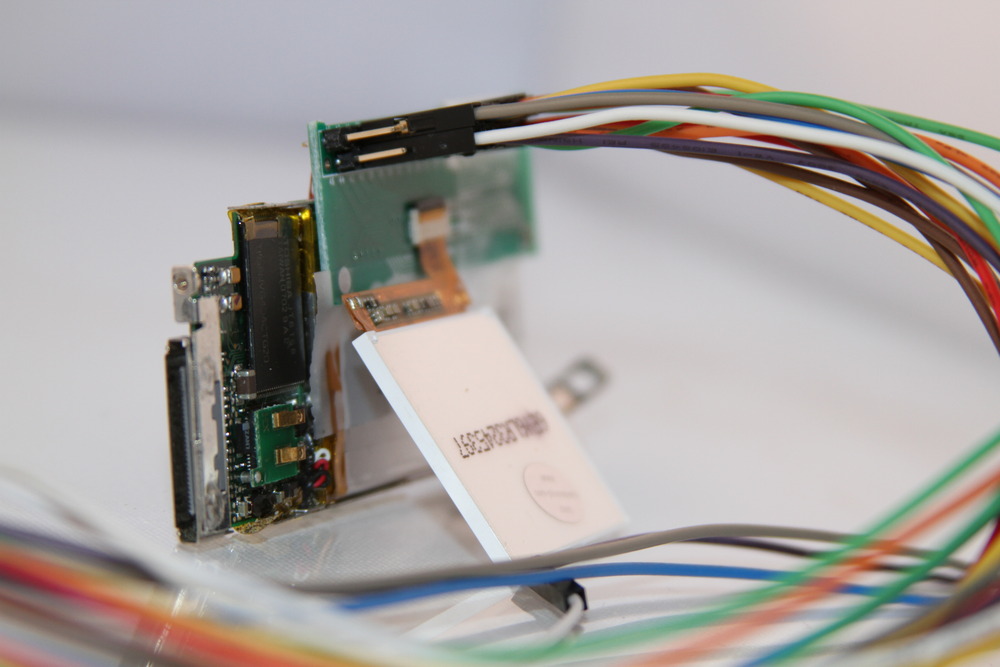
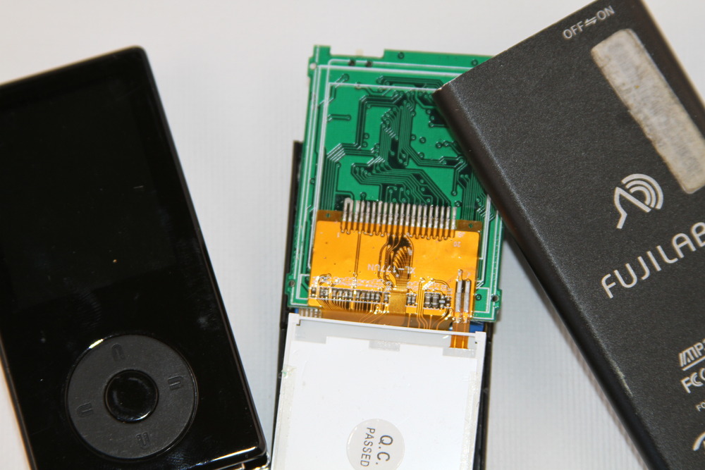
The iPod Nano 2G has a lovely little 22 pin transflective 176×132 screen. It has a 0.3mm pitch connector as seen in the iFixit tear-down. Nearly all 0.3mm ffc connectors have an odd number of pins. Apple thought different and used a DDK FF12 that is very hard to come by. After buying lots of replacement LCDs ($5 ebay + many $1 auction wins) and lots of dead/dying nano2Gs it was time bust out the fine transformer winding wire and a logic analyzer.
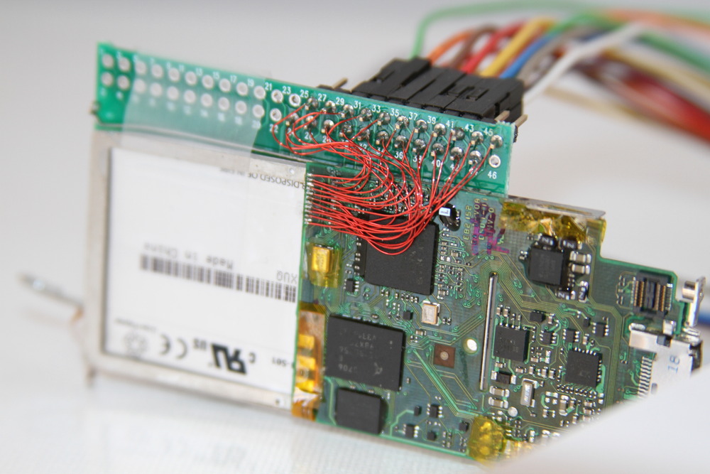
The data bus is easy to find: look for 8 consecutive bits that change all at the same time. The WR, CS and CD signals are then fairly easy to spot based on decreasing activity. As it turns out there are at least two different driver ics in these screens: A narrow one that looks a lot like a ILI9163 (8 bit wide commands, sets up blits with 0x2C) and wide one that looks a lot like an ILI9320 (16 bit commands, sets up blits with 0x22).

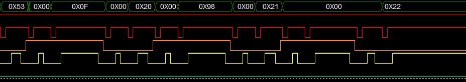
Although these controllers are similar to documented controllers they still have major differences and I needed to record an initialization sequence from a live boot in order to get them to work.
Connector pinout Nano 2G
        1        LED+ 6V
        2        LED-
        3        Frame Marker
        4        GND
        5        D7
        6        D6
        7        D5
        8        D4
        9        D3
        10        D2
        11        D1
        12        D0
        13        RD        Read
        14        WR        Write
        15        CD        Command/Data
        16        CS        Chip Select
        17        Reset
        18        GND
        19        VIO        3V3
        20        VDD        3V0
        21        ID0
        22        ID1

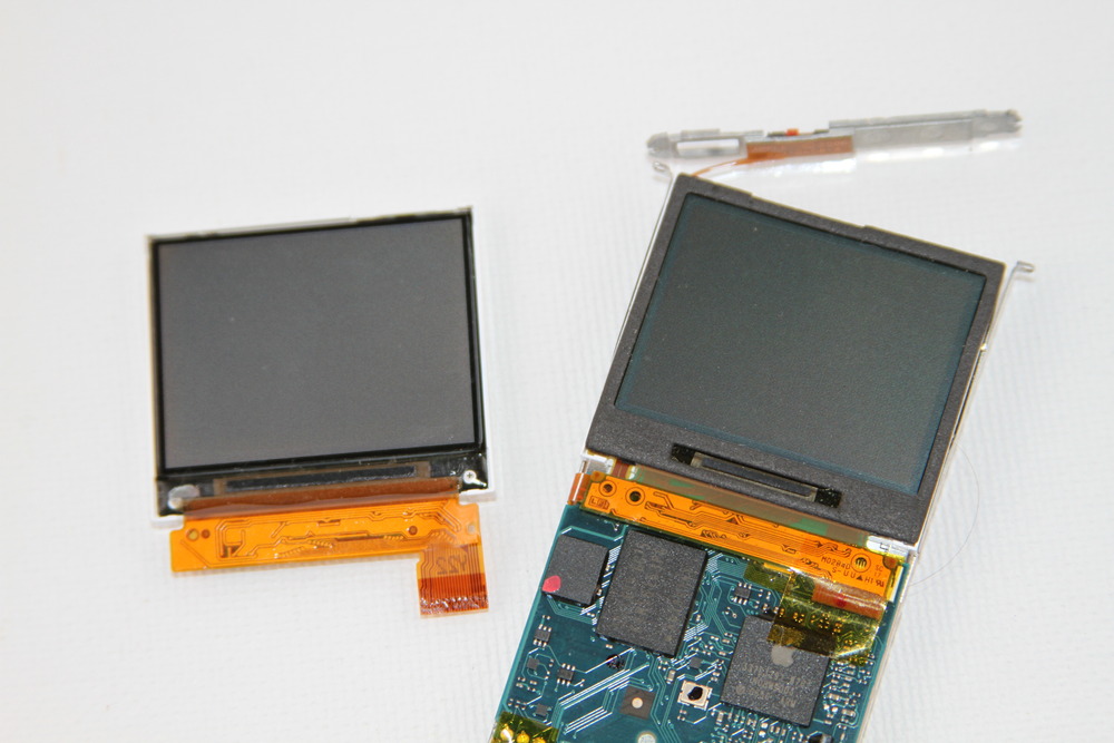
If one dismembers enough mp3 players one starts to notice patterns of part usage. One display caught my eye: it was very common in cheap 128×160 mp3 players, was a crisp and high contrast TFT, and had a hot bar solder connector that looked like it could be soldered by humans.
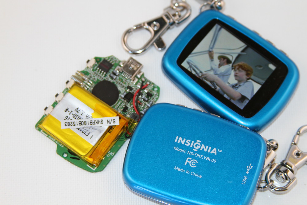

After dismembering a very nice Insignia digital photo keyframe and applying the logic analyzer the traces look very familiar. It was a ILI9163. Other devices turned up a ILI9161 and a Samsung S6D0144. All variants seem to have a very similar physical outline; another defacto standard like the touchscreen used in microtouch.They are widely available in China for $2 making them the cheapest TFT going.


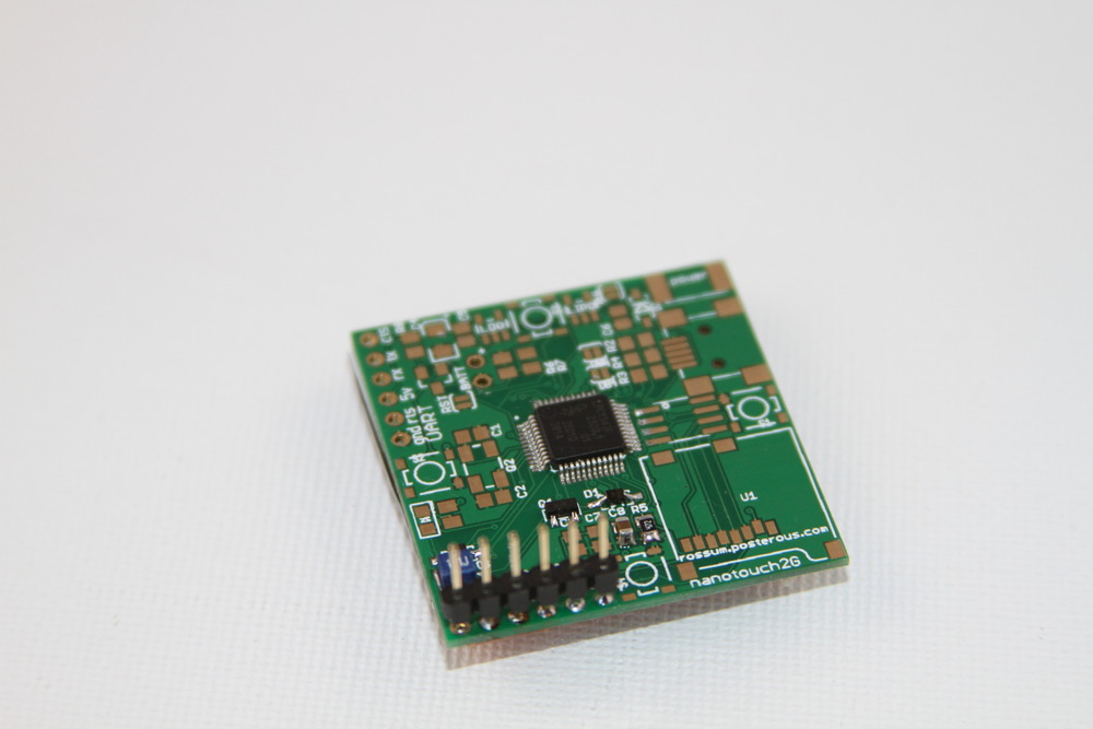
smartlcd
The smartlcd adds intelligence to a TFT 20 display. An inexpensive Arm Cortex M0 or M3 microcontroller is used to provide graphics and media processing as well as providing a high speed serial interface the 3v3 display. With additional components the smartlcd can offer a spi-flash or microSD file system and usb. One single pcb scales from bare bones serial through to a stand alone lipo battery powered device.


// Console demo
        int a[2];
        a[0] = analogRead(A0);
        a[1] = analogRead(A1);
        if (_mode == 0)
                Console.Write("X:%d Y:%dn",a[0],a[1]);
        else
                Console.Graph(0,1023UL,a,2);

        // Circle demo
        int x = random(128);
        int y = random(160);
        int r = random(70);
        int c = random(0xFFFFL);
        Graphics.Circle(x,y,r,c,1);

very good article. I was willing to ask what kind of logic analyzer are you using?
@Boyko For quick serial/spi/debugging I usually use a Logic (http://www.saleae.com/logic/) because it fits in my laptop bag. I use a ZeroPlus Logic Cube for >8 bits/>24Mhz and have started to use a sump (http://www.sump.org/projects/analyzer/) for specific high speed protocols.
Did you think this one could do the job ?
http://iteadstudio.com/store/index.php?main_page=product_info&cPath=2&products_id=221
Very cheap..
Nice little gadget indeed. This would be a cheap and easy way to add a display to my existing projects targeting 8 bit MCUs, without sacrificing too much CPU time. They usually already have a free UART that I use for debugging/PC communication.
However, I’m at a loss for where to locate those “$2 LCDs”. I’ve already checked the Chinese ebay stores i know about, but with no success. Some pointers on how to get hold of some of those TFTs would be greatly appreciated.
@no0x The CY7C68013A board looks fun and cheap and would certainly do the job although I really like supporting Saleae; it is more expensive but a nicer build and he did go to the trouble of writing pretty software.
@g3m Grab a friend who speaks mandarin and try taobao.com. We should encourage local folks like adafruit to stock these.
rossum, I looked at taobao.com and did a search on 128×160. I came up with these two hits:
http://item.taobao.com/item.htm?id=5460517340
http://item.taobao.com/item.htm?id=6893999183
The first one seems to be a development board with a nice header breakout. Are these the modules you are referring to?
Actually looks like this one might be it. Has the S6D0144 Driver chip?
http://item.taobao.com/item.htm?id=7521832951
Thanks for a really useful post as always !
Have you looked at some low-priced OLED displays?
This 1″ OLED 64K color display uses the SSD1332 controller.
https://www.mdfly.com/index.php?main_page=product_info&cPath=40_85&products_id=352
I would love to know if you have any plans of supporting similar OLED displays in the SmartLCD project !
Thanks !
Wow! Very cool stuff! I’m going to build a few of these for sure! Only problem is the display, witch one to get and where!
Would something like this be supported: http://cgi.ebay.com/1-04-65K-OLED-Color-Display-96×64-SSD1332-backlight-/380278436052?pt=LH_DefaultDomain_0&hash=item588a5c70d4
Thanks!
I’d really like to follow this. Project. Do you have twitter? I’d love BOM w/ suppliers. Sign me up! I’m ready to buy! This is great! Exactly what i’ve been waiting for! Hats off to you.
Any plans to offer this for sale as a kit or finished board? I’d love to have a few boards made and give it a try, but my SMD soldering skills are going to make parts of it a real challenge.
@Curtis Those LCDs are similar but not the same (27 and 36 pin connectors). I have ordered from that vendor before but they seem to be out of stock at the moment:
http://item.taobao.com/item.htm?id=4001769307
I will be doing a 27 and 36 pin version of the PCB, as well as one for this touchscreen:
http://item.taobao.com/item.htm?id=7219948955
@Sayan + Ramon I will post a couple of OLED boards soon.
@Matt Don’t fear the SMD soldering! It is so much fun. With the right application of flux it is easier and faster than thru hole. No flipping the board over and chasing components that fall out, just the joy of flux and fluid dynamics.
Above you say that you found different controllers in different LCDs from the different products. They were: ILI9163, ILI9161 and Samsung S6D0144. Does the project function with LCDs with all of these controllers? For instance the one you linked above that is a 20 pin, is the S6D0144, even though the TFT20.cpp seems to be calling the routines for ILI9163, will it still work? I am reaching out to my contacts in China to find a source for these and want to make sure I have all the facts before I order a bunch of them.
@Curtis The S6D0144 driver will be posted soon. I will also support the HX8309/HX8310 as soon as I can verify the driver with actual parts.
rossum, every project you post is simply too awesome for words! I can never wait to see what you do next.
@rossum What is your SMD soldering process, specifically? You mention flux, but do you mean flux paste with solder balls, or plain flux? Do you use a reflow oven or all soldering by hand? All the SMD soldering I have done has been soldering by hand; for many-pin packages like SOIC or QFP I apply solder to all the pins and use solder wick to remove the excess and fix bridges. I have a hot air feature on my soldering station but have only used it so far to fix a BGA on my old HP LaserJet’s JetDirect card, not for any new construction.
@Curtis, is there some way I can get some displays from you when you order? Can I contact you about it?
@colinb I do SMD drag soldering by hand. I very rarely use wick.
http://www.youtube.com/watch?v=Ql6Vkw5wswU&feature=fvw at 0:13 for a nice example.
@rossum Thanks for the video link. Is it critical to have a beveled soldering iron tip? The only tips I have are conical fine points. What type of flux do you use (water based, no clean, …) and do you use a pen or a syringe to apply it? Thanks.
@colinb Get a bevel tip; a tiny conical tip won’t carry any solder and is useless for SMD work. I generally use ‘no-clean’ flux from a syringe (which I clean with alcohol). Pens work too but I tend to leave the caps off.
rossum is right about the beveled (also known as a chisel or hoof) tip. The large round surface draws the solder and allows a wave formation as the tip moves along the leads. But be careful of the “no-clean” flux designation. Many flux manufacturers call fluxes “no-clean” when they are actually only low solids (rosin, or whatever material is being used to cover the parts during soldering). The critical consideration for flux selection should be acidity (sometimes known as “activity”); too much acidity will cause post-soldering reliability problems.
I write about these sorts of topics pretty regularly at http://blog.emsciences.com. You should find some items of interest there.
@Ramon Yes, I am still searching for a source for these modules, when I find them, I’ll probably order a bunch and put them up in my online store. I have been in contact with one manufacturer and they are end of life and have not heard back from a 2nd I found. I have also reached out to a contact I have in China to have him look in the market for them.
@rossum, The one mfg said they are replacing the TFT20 with a 1.77″, 33pin, HX8353D controller IC. Looks like 12 of the pins are NC which is odd unless they are trying to fit an existing standard. I’m thinking that all that would need to be changed out on the board is the larger connector. Not sure how hand solderable they are. That touchscreen looks really interesting as well as support for other larger LCDs.
@rossum The LCD here http://item.taobao.com/item.htm?id=4001769307 that you posted with the S6D0144 are you pretty confident that will work? I have a line on getting a bunch of those and want to make sure.
@Curtis The S6D0144 driver works but this 36 pin / 1mm pitch board is a little problematic: the connector is wider than the current PCB. Do you have a physical spec for these?
@rossum, I am working on getting the datasheet now. I can do the board re-design for these LCDs and the larger pinout. I plan on getting some PCBs made at the same time to go with these (and 2 others), so that isn’t a problem. Any chance we can start a dialog via email. I’d like to help build a BOM for this board, but there are a few items I’m not exactly sure what they are or what the values are. My email is cpope at wingsnwakes dot com.
@rossum, just got the datasheet and found out why it doesn’t make sense. The pitch is actually 0.9mm not 1mm as in the ad. It should just fit now. There is another 1.8″ lcd with a 1mm pitch, 27 pin, HX8310 but says 16-bit interface. I’ll get the datasheet on this one too. http://item.taobao.com/item.htm?id=7521751367 Should it work?
I have 2 of these, I hope I can use them on your board too I really can’t wait any longer to get my hands on one of your boards!! 🙂
Whoops I meant these: http://www.satistronics.com/096-128×64-oled-lcd-led-display-module-ug2864ambag01_p2871.html
@rossum, do you have a good source for the LPC1114 chips? will the code fit in a LPC1113?
@ramon, You can get them from Mouser or Digikey. The picture at mouser is wrong, but it is the right package LQFP48. Here are both links:
http://www.mouser.com/ProductDetail/NXP/LPC1114FBD48-3011/?qs=P1eGD%2f8NI1owlXN%2fIUm%252bgQ%3d%3d
http://search.digikey.com/scripts/DkSearch/dksus.dll?site=us&lang=en&mpart=LPC1114FBD48%2f301%2c1
There are other retailers…for the complete list with stock, see here:
http://www.nxp.com/#/page/content=%5Bf=/dynamic/orderportal/tid-50809_sid-71391/data.xml%5D and search for 935290789151 on the page.
Do you have (or plan to have) an online store where you sell your the things you develop- getting them as kits would be awesome !
I know many folks in my hobby club would be interested in buying
@Curtis Thanks I did check the nxp page indeed and I checked mouser, but I live in the Netherlands and I have no order that is going to exceed $75 so the shipping costs would me huge! Thanks for the response!
@Ramon van Bruggen:
Check Farnell.
http://nl.farnell.com/nxp/lpc1114fbd48-301/mcu-32bit-32kflash-cortex-m0-48lqfp/dp/1786289
I know that they are charging a ridiculous price premium on just about any parts (Farnell’s price is often 200-300% of the ‘normal’ price), but they are still the easiest way to get ‘not so common’ parts in Europe.
Referring to the TaoBao, I can get supplies from there if needed. Also you wouldn’t be Guido van Rossum would you?
I chanced upon a post that demos a breakout board for 1″ OLED
It looks similar to the SSD1332 controller based board sold by mdfly.com.
However I don’t know Chinese to understand what is going on… thought you might have an idea.
http://bbs.yleee.net/viewthread.php?tid=3273&extra=&ordertype=1
I have a spare board and an OLED screen that I can send over to you if it helps !
rossum, you are awesome !
If someone needs it, I made a project on mouser with all the components (apart from the LCD), I’m not quite sure about a few components (like the inductor) so if you could check it and see that I made no mistake
http://www.mouser.com/ProjectManager/ProjectDetail.aspx?AccessID=d9b3cef564
I have a question though : you say that we don’t need a special programmer for the Cortex. Do you program it using the USB port or directly via the Arduino ? That’s a bit not clear, but I guess I’ll have to dig into the code.
Rossum, are there any plans for a kit?
@catblack, I would consider putting together a kit of at least an LCD and a PCB if rossum wouldn’t mind. That combined with a BOM from mouser would be pretty much all you’d need. Rossum, what do you think?
@Kamel Thanks for putting together the BOM. There are a few errors that are my fault: It needs a 12Mhz crystal for USB (no crystal required for serial) and a 100uh power inductor for the boost circuit. I will make a couple of mouser BOMs for the different configurations.
You won’t need a special programmer for the Cortex, it can be done by the Arduino hardware or a serial cable. I will post an application that flashes the device in the next week or so.
Really looking forward to updates!
According to iPodLinux:
http://ipl.derpapst.eu/wiki/Generations#iPod_Nano_Second_Generation_.28Nano2G.29
, the iPod nano 2G uses a “Sharp/Optrex/Toshiba” display. A quick search for “Optrex” and “176×132” leads to their only 176×132 pixel LCD controller product, the T-51991GD015-MLW-AIN. I found the datasheet at:
Click to access T-51991GD015-MLW-AIN.pdf
The pin-out looks the same as yours…
Hope this is useful!
Mechanical drawing is at:
Click to access T-51991GD015-MLW-AIN_drawing.pdf
Where did you get the DDK FF12 connector for the iPod 2G LCD?
i bought two of this lipo batteries http://cgi.ebay.com/ws/eBayISAPI.dll?ViewItem&item=270661353919#ht_2279wt_1139. will this circuit able to charge them? Because i’m not sure how lipo charging works
@Boyko Those will work. See http://ww1.microchip.com/downloads/en/DeviceDoc/22036b.pdf
@Bokyo, Rossum: The MCP73811/2 has no charge termination control (see §4.6). I would recommend the MCP73831/2 instead: http://ww1.microchip.com/downloads/en/DeviceDoc/21984e.pdf, see §4.6
Agreed. MCP73831/2s are only slightly more expensive and have a nice STAT pin to indicate termination; kit versions of the smartLCD use these.