A Smarter Display

Connecting display to Arduino can be expensive, complicated and unsatisfying. The smartlcd attempts to make it cheaper, simpler and more fun.
 
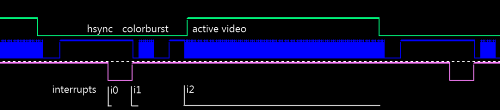
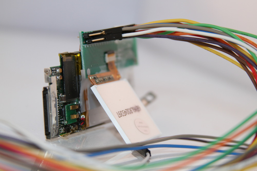
There are lots of interesting displays hiding in cell phones, cameras, mp3 players and various other devices. In this post we will be looking at two of my non-Nokia favorites: The iPod Nano 2G display and the so called “cheapest TFT in the world”. Then we will be making a gadget that hopefully does something useful with them.

To repurpose a display we need to determine its interface mode (serial/parallel), pinout and driver ic. If the display has a nice part number printed on the side then you might get lucky and have the interwebs answer all your questions. Much more often than not you have to do it the hard way.

Count the number of pins on the connector. If there are 8-16 pins it is almost certainly a 8 or 9 bit spi interface. Find the LED supply pins (almost always the thickest traces on the flex) and give them the respect their elevated voltages deserve. Attach a logic analyzer to a live system determine the spi clk (wiggles most), the spi mosi (wiggles second most), the spi select and the reset (wiggles once). See this example.

If you have 20 or more pins you have an 8 bit parallel interface. If you have 24 or more chances are it is 16 bit parallel. Many displays have the ability to run in both serial and parallel modes that can be selected with one or more external pins. If you are short of GPIOs this is a good option.

iPod Nano 2G
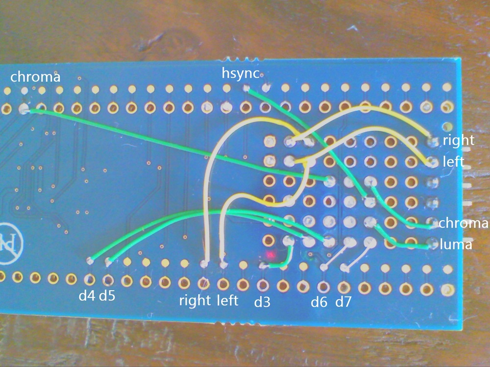
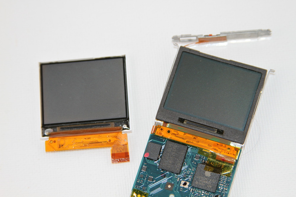
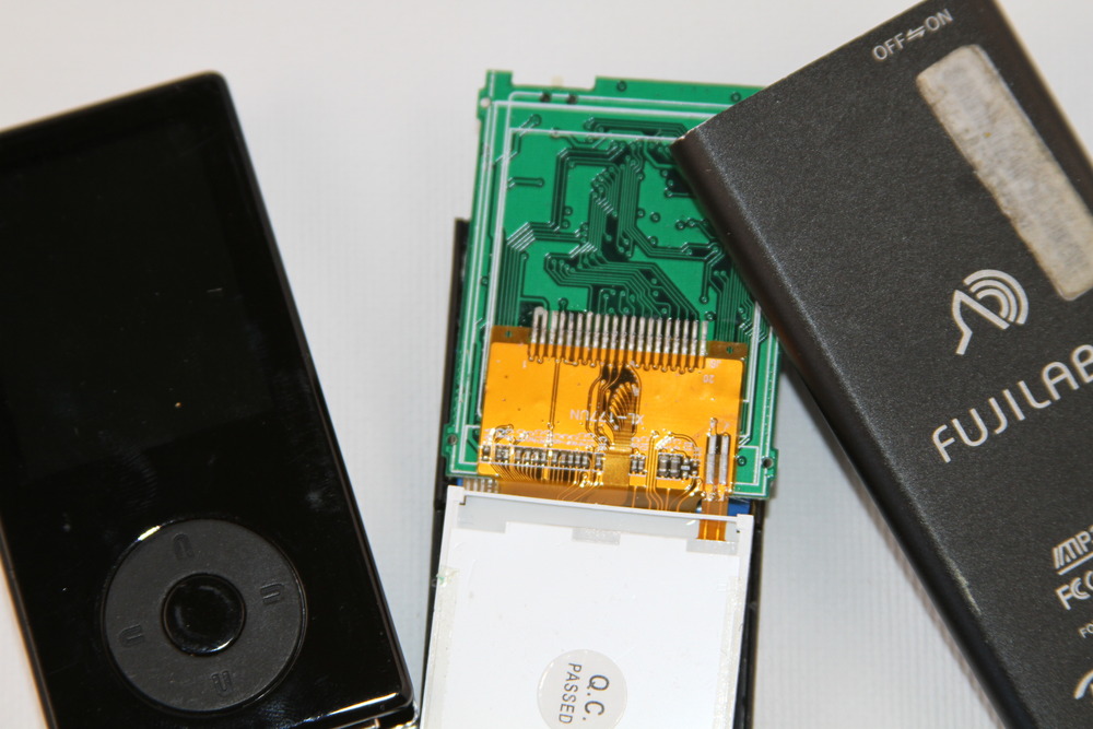
The iPod Nano 2G has a lovely little 22 pin transflective 176×132 screen. It has a 0.3mm pitch connector as seen in the iFixit tear-down. Nearly all 0.3mm ffc connectors have an odd number of pins. Apple thought different and used a DDK FF12 that is very hard to come by. After buying lots of replacement LCDs ($5 ebay + many $1 auction wins) and lots of dead/dying nano2Gs it was time bust out the fine transformer winding wire and a logic analyzer.
 

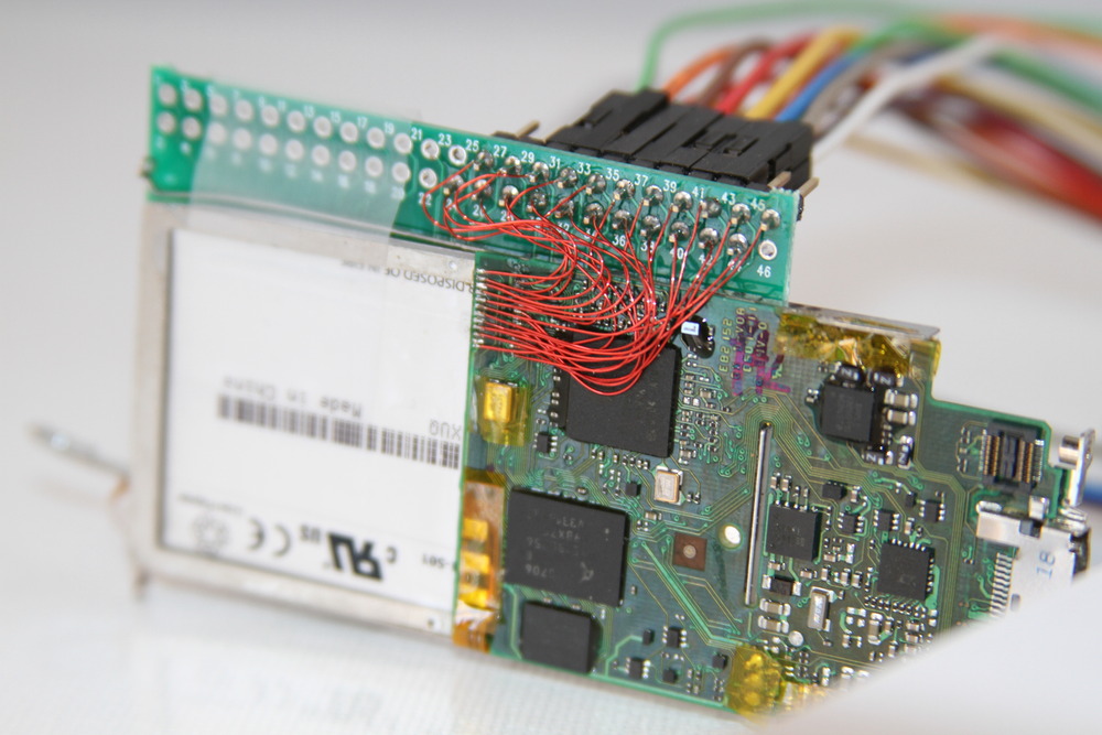
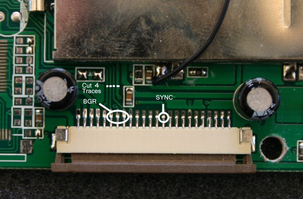
The data bus is easy to find: look for 8 consecutive bits that change all at the same time. The WR, CS and CD signals are then fairly easy to spot based on decreasing activity. As it turns out there are at least two different driver ics in these screens: A narrow one that looks a lot like a ILI9163 (8 bit wide commands, sets up blits with 0x2C) and wide one that looks a lot like an ILI9320 (16 bit commands, sets up blits with 0x22).
 

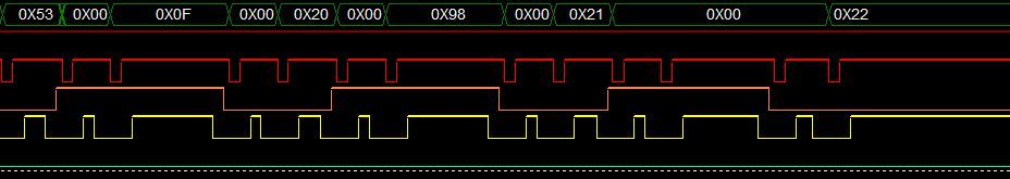
Although these controllers are similar to documented controllers they still have major differences and I needed to record an initialization sequence from a live boot in order to get them to work.

Connector pinout Nano 2G
        1        LED+ 6V
        2        LED-
        3        Frame Marker
        4        GND
        5        D7
        6        D6
        7        D5
        8        D4
        9        D3
        10        D2
        11        D1
        12        D0
        13        RD        Read
        14        WR        Write
        15        CD        Command/Data
        16        CS        Chip Select
        17        Reset
        18        GND
        19        VIO        3V3
        20        VDD        3V0
        21        ID0 
        22        ID1
Preview of an upcoming project using iPod Nano 2G screens:
The TFT 20
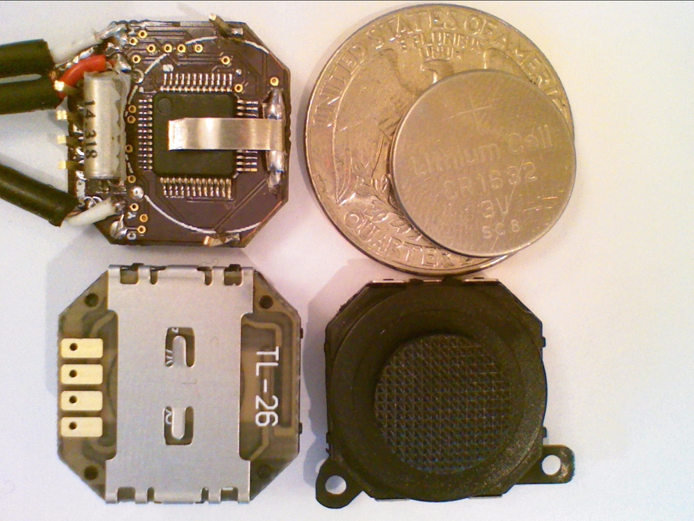
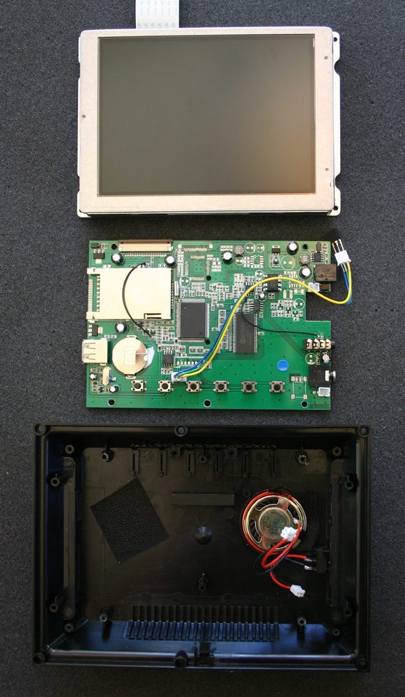
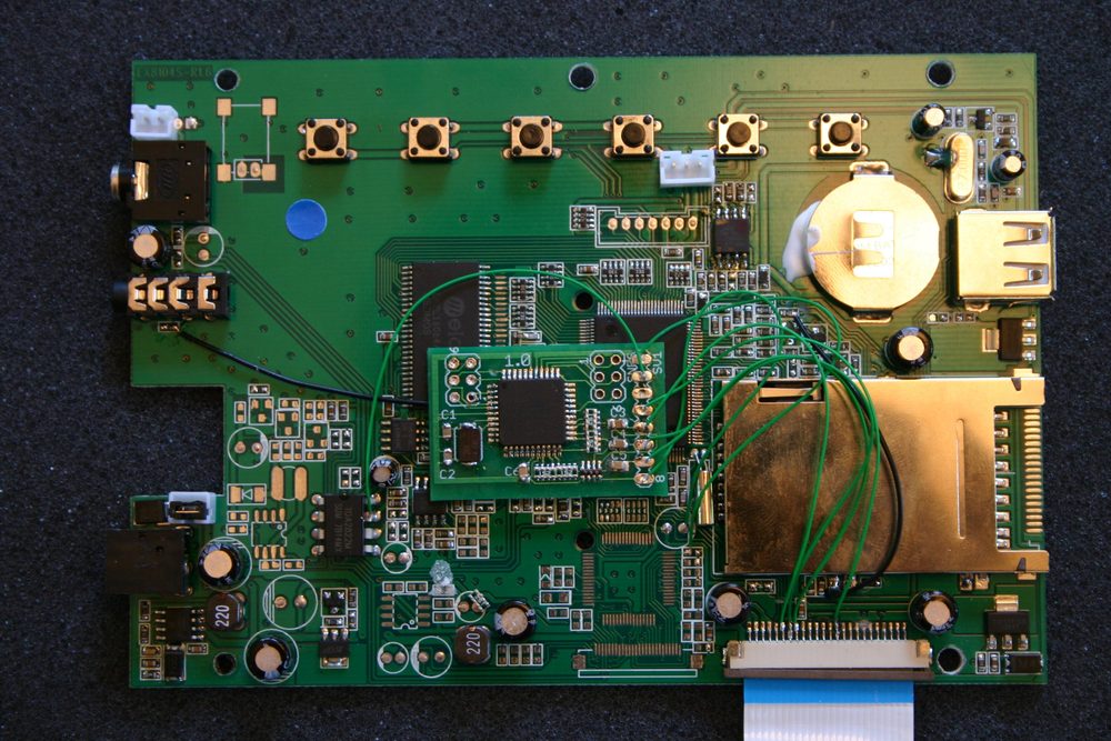
If one dismembers enough mp3 players one starts to notice patterns of part usage. One display caught my eye: it was very common in cheap 128×160 mp3 players, was a crisp and high contrast TFT, and had a hot bar solder connector that looked like it could be soldered by humans.

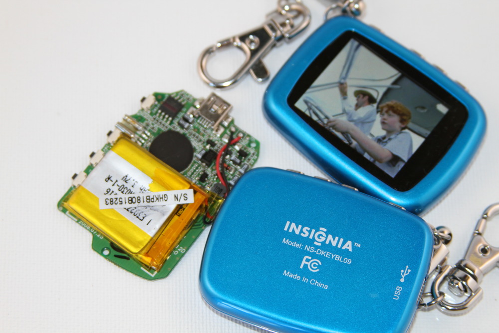
After dismembering a very nice Insignia digital photo keyframe and applying the logic analyzer the traces look very familiar. It was a ILI9163. Other devices turned up a ILI9161 and a Samsung S6D0144. All variants seem to have a very similar physical outline; another defacto standard like the touchscreen used in microtouch.They are widely available in China for $2 making them the cheapest TFT going.
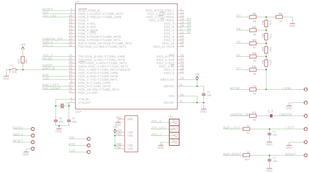
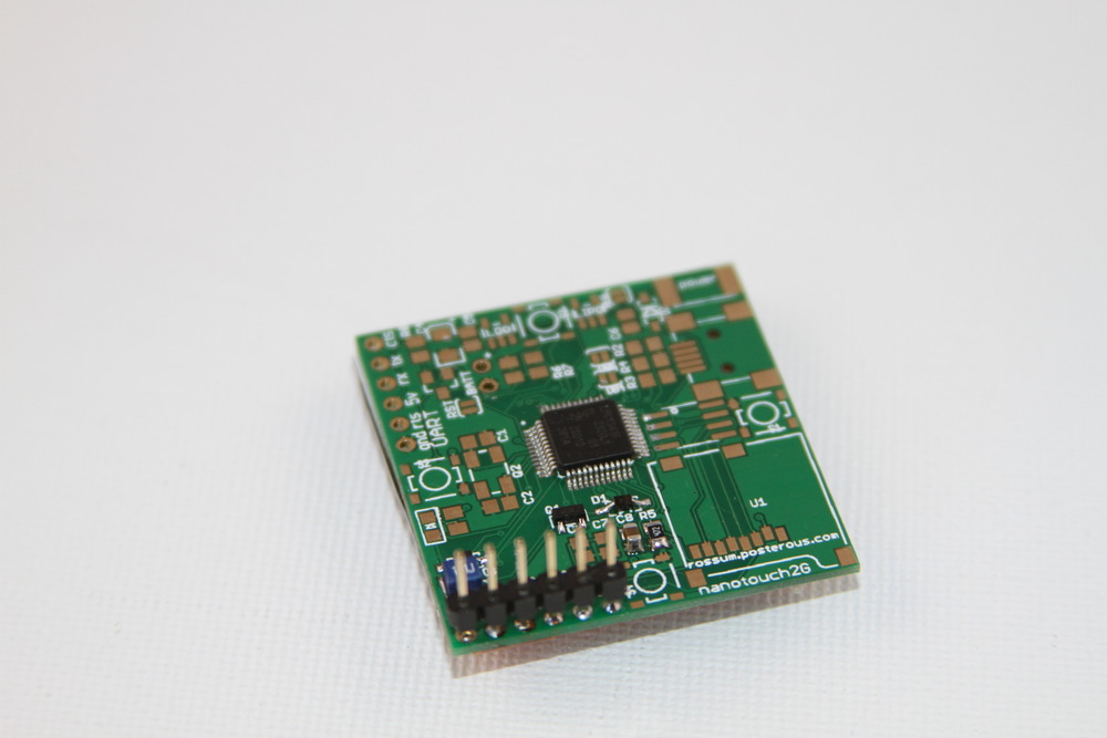
So how can we make this lovely little screen useful to say an Arduino enthusiast? It needs 3v3 io on 14 pins connected to a 1mm pitch hot bar solder connector, a 6v boost converter to supply the leds, drivers, apis etc to make it useful. Not the simplest thing to do on a breadboard.
Thats where smartlcd comes in.
 
smartlcd 
 

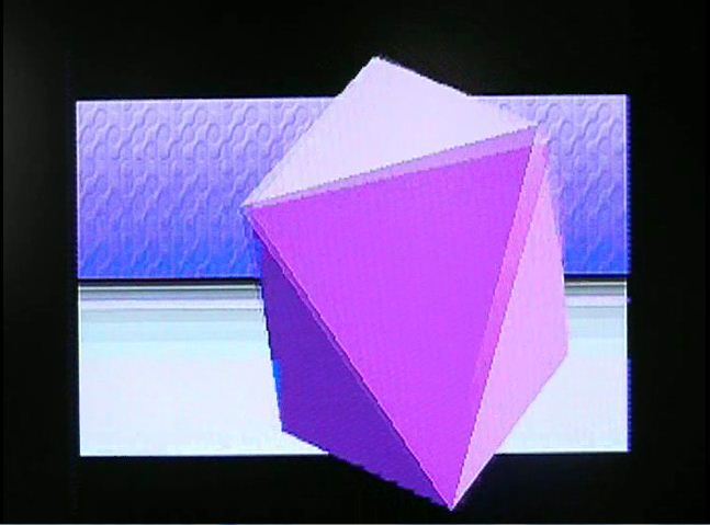
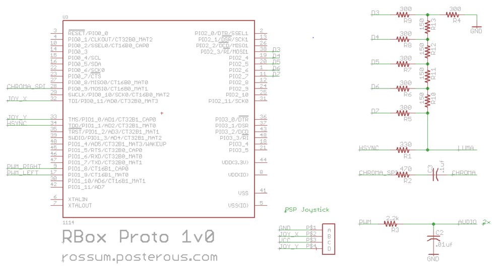
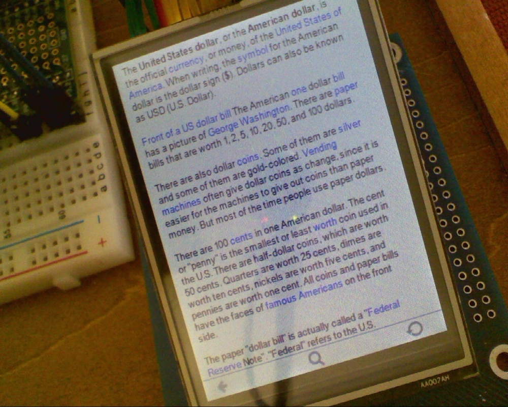
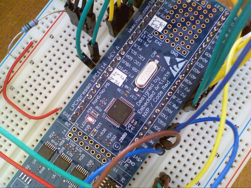
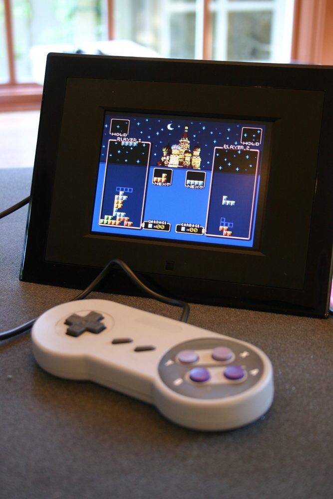
The smartlcd adds intelligence to a TFT 20 display. An inexpensive Arm Cortex M0 or M3 microcontroller is used to provide graphics and media processing as well as providing a high speed serial interface the 3v3 display. With additional components the smartlcd can offer a spi-flash or microSD file system and usb. One single pcb scales from bare bones serial through to a stand alone lipo battery powered device.
A minimal configuration with just the backlight boost converter and serial interface:

2010-10-18_0002

smartlcd uses a serial link to connect to Arduino and other devices The serial link runs a slip framed, software flow controlled RPC at 1MBit. 5v to 3v3 level conversion is not necessary; the smartlcd inputs are 5v tolerant and can plug directly into the Arduino RX and TX pins. Because it is connected to the serial interface, the smartlcd can reprogram the Arduino and under the right circumstances the Arduino can be reprogram the smartlcd. The smartlcd can also be configured to be reprogrammed via USB and you don’t have to know anything about arm or own a arm development kit to build one.

Img_6286

The client does not have to be a Arduino; the smartlcd can connect to virtually any serial device or USB. However smartlcd makes it very easy to display text, graph values and draw graphics quickly on Arduino:
// Console demo
        int a[2];
        a[0] = analogRead(A0);
        a[1] = analogRead(A1);
        if (_mode == 0)
                Console.Write("X:%d Y:%dn",a[0],a[1]);
        else
                Console.Graph(0,1023UL,a,2);

        // Circle demo
        int x = random(128);
        int y = random(160);
        int r = random(70);
        int c = random(0xFFFFL);
        Graphics.Circle(x,y,r,c,1);

Fully loaded versions of smartlcd can decode JPEG, PNG and will be able to decode some forms of video. Source code, schematics and Eagle files: https://sourceforge.net/projects/smartlcd/.

Until next time


Advertisement

Building the RBox.

I finally got around to assembling a stand alone version of the RBox. As some of you correctly noted building a videogame for the price of a latte that depends on a $30 dev kit is cheating a bit. This version is self contained and while not practical or useful it is at least fun to build.

The design sandwiches a lithium button cell between the psp joystick and the pcb. It adds a single button that serves as both the power switch and a fire button. 2 axis control + fire may seem a modest level of input but modern standards but if it was good enough for Atari is is good enough for me.

Thin bendy metal on top of the cpu and on the bottom of the joystick provide a suprisingly effective friction fit for the CR1632 battery. Don’t try to solder directly to the metal on the bottom of the joystick. When running a game and playing audio the device uses about 28ma so I get about 4 hours of continuous use from the CR1632. Feel free to use a CR1616 or CR1620 for a slimmer look and more frequent battery replacement. 

The schematic is virtually identical to the prototype with a few exceptions. The joystick VCC line is connected to a GPIO rather than  VCC to reduce power during normal operation and especially during deep power down. The fire button is connected to the WAKEUP pin that brings the beast back from deep power down. The code will deep power down the RBox after 3 minutes of inactivity. While turned off the RBox uses about ~200na as far as I can measure on my crappy meter. The board supports both composite and s-video.

If you don’t feel like making your own pcb order them from http://dorkbotpdx.org/wiki/pcb_order. This is simply the cheapest and best way of getting pcbs in small volume. Nobody else comes close. Unless you really like what ferric chloride does for your sneakers there is no reason not to use these guys.

New code, schematic and pcb posted on https://sourceforge.net/projects/rbox/. If you would like a kit post a comment and if there is lots of interest I will see if I can get one organized.

Until next time

Screen Play: Lots of other screens for microcontrollers.

If you enjoy LCDs and microcontrollers chances are that you have tinkered with the ubiquitous Nokia 6100 screen. I love the fact that a youtube search for “Nokia 6100” produces may more AVR and PIC hacks than phones. In a bit of a departure from my normal projects this is the first in a series of posts on lots of other little known display choices that are better, cheaper and just more fun.

Despite its popularity the Nokia 6100 display has a few problems:

  1. Small (132×132)
  2. It is a CSTN (passive matrix) display leading to ghosting if things move quicky. Koopas are especially lethal if nearly invisible.
  3. Limited color depth of 12 bits (4096 colors + dithering on some displays).
  4. It comes with 2 incompatible driver ics (Philips or Epson).
  5. Not cheap: $15 from sparkfun or (gasp) $35-$42 for breakout boards.
  6. A fiddly, relatively uncommon 0.5mm connector that tends to tear off expensive breakout boards rendering them useless.
  7. Needs 6V for the backlight (2 leds in series).

The Nokia 6100 first shipped in 2002. Of the hundreds of models of phones from nokia (yes, hundreds) surely there are other screens of interest? A quick check in my junk phone archive of hundres of phones (yes, hundreds) turned up a few interesting candidates.

A quick check of the schematics turned up a series of SPI driven displays connected to 10, 22 and 24 sockets.

Nokia 1600: Although the 1600 screen uses the same 10 pin connector (Hirose DF23-10DS) as the Nokia 6100 the pinout is very different – so different in fact that if you plug a 1600 screen into a 6100 phone blue smoke will be emmitted and your phone will become a purely decorative item. The screen is speced as 96×65 CSTN.

Nokia 6101: Two displays here. A 96×65 CSTN caller id screen with backlight leds on the phone pcb (fail/win) and nice big one with a 22 pin 0.5mm connector (Hirose DF23-22DS) that is a 132×162 TFT (acvtive matrix) display.

Nokia 2760: Two displays again: an oh-so-cute teeny 96×65 blue monochrome display with the 10 pin connector and a 132×162 TFT with a 24 pin 0.4mm connector. These are not the Hirose DF30 series; I am still looking for a definitive source.

We know they are SPI, so lets get them wired up to a logic analyser and see if we can identify what controller they use. Once wired up we record the traffic going two and from the LCD as the phone boots. Looking at the traces it is clear that all these phone used a fairly uncommon 3 wire mode of SPI to determine what display is attached.

After an initial 0x11 (Sleep Out) 9 bit SPI command the 0xDA,0xDB and 0xDC (Read Device ID) commands are followed by 8 extra clocks during which the MOSI line is driven by the LCD. In this 3-wire SPI mode the MISO is really SISO (slave in slave out) and is usually not supported by hardware so we will need to bitbang during this discovery phase. This is the way Nokia 6100 phones can tell the difference between the Epson controller (that does not respond to RDDID) and the Philips controller (that does).

Rddid

Looking at SPI recordings reveal that the controller on the large screen looks an awful lot like the Philips PCF8833 controller in the 6100. Searching by RDDID manufacturer id 38H turns up the Orise SPFD54124B for the 6101 screen. It has a lovely 262k frame buffer and supports a 12,16 or 18 bit color format. Ironically googling this controller led to a great site that details this and other earlier phone displays. The caller id screen seems to be a SED1565 or similar, the 1600 seems similar to the Philips.

The 22 and 24 pin displays support SPI or an 8 bit paralell interface selected by a p/s pin. SPI is usually fast enough for smaller screens unless you are really perf sensitive. SPI means fewer pins on the mcu, fewer lines you need to convert from 5v to 3.3v etc.

Now the really good news. The 6101 displays are really cheap on ebay. <$3 with free shipping much of the time. They address problems 1) thru 5) listed above. The 1600 screens are also cheap if you need something small – dealextreme has them for <$5. 1200 displays are pin and code compatible with the caller id screen an very low power if you don’t use a backlight.

All these and more in action:

The breakout board above supports both 10pin pinouts as well as 22 0.5mm and 24 0.4mm pinouts. It has a built-in boost converter for generating various led supply voltages controlled by pwm from the mcu. It has a sense pin to allow you to measure the backlight current and adjust it accordingly by varying pwm duty cycle.

nokiaSuperBreakout.pdf
Download this file

The software in the demo detects when a display is attached, selects the right driver and runs an appropriate graphics app: Wireframe 3D for mono screens, the reference Rossum icosohedron and a raycast lattice for color. As always code and schematics/pcbs will be posted on Sourceforge.

In the next post, I will look at displays from several non-Nokia phones, the worlds cheapest TFT and the Ipod Nano 2G.

Until then


UPDATE: PCB, schematics and code for AVR and NXP posted at https://sourceforge.net/projects/nokiasuperbreak/.


RBox: A diy 32 bit game console for the price of a latte

Uses the smallest and cheapest 32 bit CPU to generate 3D graphics and sound.


The RBox is a game console that is simple enough to build on the prototype area of a dev kit; no pcb required just a crystal, a few capacitors and resistors.

Rboxproto

 
Features:

320×240 composite or s-video output generated entirely in software
256 colors with standard palette, up to 8k colors
8 bit 15khz stereo audio
~$1 Analog joystick
~$1 CPU

A bit of history…
Ever since the Atari VCS generated video by Racing the Beam i have wanted to build something that generates video on the fly. There have been lots of great diy examples of this in the intervening years (Rickard Gunee’s Picpong and SX Tetris, the lovely Uzebox) but the arrival of the ARM Cortex M0 parts from NXP rekindled my interest. The NXP LPC111X family is smallest 32 bit CPU. It is an ARM Cortex M0, the same device I used in the Wikipedia reader. This family of devices starts at under $1.

The LPC111X parts have ample horsepower for black and white video, as many less powerful chips have done in the past. At a max clockspeed of 48mhz they require 2 clocks to access memory or gpio so you could write a blit loop fast enough for 320 horizontal resolution (each pixel at 320×240 takes 8 cpu clocks, enough time for read/palette lookup/write/test/loop). Add a couple of resistors for a DAC, add sync pulses and you are in business. Overclock to 57.27272 and then you are a multiple of the chroma carrier and can generate colorburst and manipulate chroma phase: Now I had nice color bars but it wasn’t clear how generalize this to a practical system that could be programmed to generate interesting and useful images.

The real breakthrough came when I realized I could re purpose SPI to manipulate chroma phase while the cpu used gpio to write luma. SPI also has a 16 byte fifo on these parts which allowed chroma writes to be queued relieving pressure on the luma timing. With SPI emitting bits at 1/2 the cpu clock rate I could get 8 bits per chroma clock, enough to do 8 different phases for 8 different hues. All the other 248 combinations of those bits generated other hues and levels of saturation, suggesting a palette of some sort might be useful.

Color generation solved, now I needed graphics. A frame buffer was out of the question: at 8 bits a 320×240 frame buffer is 75k. These devices have 2k to 8k total memory so another approach is needed. After fiddling with tiles (as in Uzebox) I eventually settled on a line buffer approach where the application sends individual lines to the video driver for display, allowing code that looks and feels like it is working with a framebuffer without the actual memory.

There are 2 pixel formats supported: 5 bits of luma with 3 bits of chroma index or 4 bits of luma with a 4 bit chroma index. The chroma indexes map to the actual 8 bit value emitted by SPI. The chroma palette can be changed every line allowing up to 8k colors on the screen at the same time. With 8 bit color filling the line buffer is simply a matter of dealing with 1 byte per pixel blitting and things like smooth scrolling become very simple.

The video driver generates 3 interrupts per line: i0 at start of the line to pull hsync and emit an audio sample. 1 pcm sample gets emitted per channel per scanline at 15.7khz which is the line rate of ntsc. i1 happens at the end of hsync. The driver releases hsync and feeds the colorburst data into the SPI fifo then returns. The active video interrupt i2 actually emits the pixels and uses about 70% of the cpu.
Scope
Much as I love this CPU there were a few wrinkles. At this clockspeed, it needs 3 wait states to access flash. If you execute code from flash on this part you can never be sure when those wait states will slow you down: the same code may run at different speeds depending on its position in flash. Really bad if you are writing a blit loop that has really tight timing requirements like generating ntsc in software. The solution was to copy the critical routines to RAM where they run without any wait states.

Other devices like the Cortex M3 based LPC13XX and the LPC17XX have flash accelerators and single clock gpio writes. The LPC17XX also has DMA that makes all this sort of thing really easy – 640×480 component video should be possible. Although more expensive than the M0 parts, they are still ridiculously cheap.

About the demo video

Tile
Scrolling around a 8192×2048 map of a certain hedgehogs homeworld. The demo uses the analog joystick as input, features single pixel horizontal and vertical smooth scrolling and runs at at 60fps. The audio in the background (the music, not the leafblower) is coming from the device.

Particle

500 particles spraying at random from two sources over an animated background. The texture in the back is being generated every line by multiplying the luminance of a blob pattern by sin(y). Single cycle multiplies take a lot of getting used to; it is often faster to multiply than to use shift/add “optimizations”. 60fps.

3D
Platonic solids float over an animated 3D plane with weird patterns in the sky that gratuitously change color. The 3D models are rendered scanline by scanline and composited with the dynamically generated backgound. Once again, because we don’t have a frame buffer, we get 60fps with no tearing.
How to build

If you want to make your own I have included the schematic and the code. I built the prototype on a LPCXpresso devkit available at Digikey, you will need to replace the stock 12mhz with a very common 14.318mhz crystal.  I bought a reel of these so if you can’t find one I will send you one. The analog joystick is a replacement part from a PSP. $1ish on ebay. The wiring photos are a little tricky to follow, check the schematics for a clearer version.

Protolayout
Protolayout2
Rbox1v0schematic
Source for the LPCXpresso/Eclipse project is posted on https://sourceforge.net/projects/rbox/

I will be doing a PCB version so for those squeamish about little green wires can hang on ’till then.

until next time,
Rossum.


Wikipedia Homebrew device features Cortex M0 processor, all human knowledge.

Gotta love Wikipedia. Gotta love really cheap, powerful Microcontrollers. They are even more delightful when combined.

This is a prototype of a cheap offline wikipedia reader based on a new NXP ARM Cortex M0 microcontroller. It renders offline dumps of Wikipedia or other text formats (books, html etc) with a simple touch interface. The dumps are stored on a microSD card and are rendered on a inexpensive touchscreen LCD. I will publish full schematics, PCB layout and source code to a final handheld version that looks an awful lot like the Microtouch.

The Software

An offline grinder tool converts xml dumps from wikipedia and other sources into a compressed text layout format that is digestible on a small device. The hard part is decompressing and drawing the text with few cycles and very little RAM fast enough for it to feel like a responsive little consumer electronics device rather than a lumbering PC. The keys to this turned out to be a spatial index that allowed fast rendering of segments of a page and hugely simplified compression. The text renderer uses subpixel positioning to help make teeny fonts readable without slowing down drawing.

The Hardware

NXP are onto something good with these ARM Cortex microcontrollers. The are cheap in onesies (<$2), fast (50Mhz), have plenty of memory (32K flash, 8K sram) and have a really nice dev kit (LPCXpresso) with Eclipse based tools and delightful Serial Wire Debug. Hardware breakpoints. 12K gates. Bloody amazing.

This project uses the LPC1114 Cortex M0 but the PCB will also take a LPC13XX Cortex M3 part that is faster (72Mhz) and has full speed usb. The prototype uses a LPCXpresso kit with lots ‘o jumpers and a ILI9325 based LCD, the same as the Microtouch.

What about the AVR?

As it turns out, this also runs just fine on the AVR based Microtouch classic hardware. It isn’t quite as zippy but still works well. The code isn’t really optimized yet and there is probably room for improvement on both platfotms. You might expect the Cortex M0 version running at 48Mhz to be 4 times as fast. It isn’t. The M0 always requires 2 clocks to read or write GPIO (unlike a single clock for the AVR) so the LCD blit loops are at best twice as fast. Code size is about the same as one might expect.

For those of you who have built your own Microtouch device I will make sure the classic hardware is fully supported. For those of you who have not built their own Microtouch yet I hear that there might be a kit in the works. Watch this space.

Until next time,

Update

Code and schematics posted at http://www.lpc1100challenge.com/detail/316


Teeny AVR Media Thing – the Nanotouch

How small can something get and still be useful? This little experiment uses a 96×64 OLED display with a click screen interface that may not be useful, but at least its fun.

Like the last project, this uses an 8 bit AVR. This time it is a Atmega32u4 that is cheaper and smaller than the Atmega644p used in the last project and has 32k flash, 2.5k RAM and full speed USB in hardware.

The screen itself is a beautiful little thing that uses a SSD1332 controller. These can be found on ebay, I have also seen them in China for $2. They are fragile – if you build one of these yourself you might want to buy a few spare screens or wait until I redesign the board so it does not need to flex as much.

The screen sits on 4 tact switches that provide input to the user interface. Movies and UI transitions are streamed from a microSD card.

The 3D demos are an homage to the brilliant yoomp  and of course to John Carmak for establishing the whole first person shooter cultural phenomenon.

Schematics, PCB and source code on Sourceforge at https://sourceforge.net/projects/nanotouch/


AVR homebrew device with iPhone aspirations

Can you make an iPhone out of an AVR? No. Can you get a surprising amount of functionality out of a humble 8 bit processor and a cheap touch LCD? Yes.

The iPhone runs more than 30 times faster (417Mhz ARM vs 12Mhz AVR) and has more than 30,000 times as much ram RAM (128M vs 4k) yet this frumpy little device can ape some of the iPhones neater tricks.

Hardware
320×240 LCD with 4 wire resistive touch screen – a ELT240320ATP variant from a dead Sylvania MP3 player – uses a ILI9325 controller.
12Mhz Atmega644 CPU with 64k Flash and 4k RAM – demo fits in 32k.
USB connector for PC communication and charging.
Lithium polymer battery with software controlled power.
Software controlled backlight.
SD Micro slot.

Software
LCD driver to support blitting image decompression and smooth scrolling.
Z-sorted span 3D engine with zero overdraw.
Basic UI framework for gadgets and poorly drawn pictures.
USB mouse or keyboard HID support.
Sampling profiler.
Movie playback.
Sprite engine.

Tricky Bits
4K of RAM might sound like a lot but it isn’t. Getting a 3D renderer to fit comes down to the representation of the active triangle edges – this engine uses 16 bytes for a double sided edge so you can have lots of triangles on a horizontal scanline and still run the whole thing in 8k of Flash and 512 bytes of RAM.

Pacman just fits in 8K flash and 512 bytes of RAM. It uses the sprite engine and runs at > 60fps.

None of the images or animations ever linger in RAM, the go straight from the SD card to the screen. The SD card is a wonderful alternative to RAM. Reading a 512 byte block takes ~1ms; not snappy but plenty fast enough for human interation.

At 3.3v, the Atmega644 is limited to about 12Mhz. Pretty pokey when you consider you can buy a  50Mhz ARM Cortex-M3 with the same flash and ram for about 1/3 as much as the 644. Don’t get me wrong; I love the Atmel parts but a little more CPU would not go astray.

Source
Source code, demo files, Eagle PCB and schematics at https://sourceforge.net/projects/microtouch/

Uzebox/Digital Photo Frame love child


Gotta love the Uzebox. Good old fashinoned fun. But now that my main TV has nearly a dozen devices in the AV switch loop I need a stand alone version of my favorite homebrew videogame.

I picked up a Sunpak 5.6 inch digital photoframe from Fry’s for $20 (online for < $25). Inside a resonably attractive case was a Sharp LQ056A3AG01 lcd, audio amp, speaker and power supply; just the thing to host a stripped down Uzebox parasite.

The parasite uses a ATMega644p but does not need the AD725 RGB to NTSC coverter as we will be driving the lcd directly. I opted for surface mount resisitor nets for the D to A ladder because
i) I had some lying around
ii) It needed to be small
iii) I hate drilling holes
iv) I hate soldering 805 resistors

I needed to cut 4 traces (RGB and SYNC) on the board near the lcd’s FPC connector (note that this is a zif socket, pull out the dark brown bit rather than yanking on the cable) to get the video signal into the lcd.  There are 7 attach points – VCC,GND, Audio to the TDA2882 amp, RGB and SYNC.

I drilled a hole in the case between and inserted a SNES controller cable, knotted it for strain relief and soldered the 5 wires (VCC,GND, CLK, Latch and Data) to the parasite. Double sided tape holds the beasty in place.

Close case, enjoy. $20 for the photo frame, $7 for the ATMega644p,  $2 for crystal, caps and resistors, $3 for the controller, $1 for the homebrew board.