S.A.M. 2600

A software speech synthesizer for the Atari 2600. Make your 2600 talk! Sing! Say rude words!

Add voice to your own games and relive the glory days when computer speech had a charming personality and bounded intelligibility.

Hello

See it in action on YouTube. Source code at https://github.com/rossumur/SAM2600

A Brief History of Speech Synthesis

While mechanical speech synthesis dates back to the 18th century, the first successful attempt based on electronics was ‘An Electrical Analogue of the Vocal Organs’ by John Q. Stewart in 1922. It was capable of saying such interesting things as mama, anna, wow-wow, and yi-yi.

Stewart Circuit

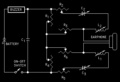
His circuit consisted of a buzzer to simulate the vocal cords and a pair of oscillators to simulate the resonance of the mouth and throat. By varying the capacitance, resistance and inductance of the circuit he could produce a series of vowel-like sounds; probably the very first example of circuit bending. I would love to see someone recreate this and learn how to play it.

These resonance frequencies are known as formants. The human vocal tract has lots of potential for complicated resonances in the mouth, throat, nasal cavities etc. The mouth formant (f1) and throat format (f2) are critical to creating sounds that are recognizable as speech. The ratio on f1 to f2 define the sound of various vowels.

The overall pitch or fundamental frequency of speech comes from oscillations of the vocal cords: the buzzer in this model. Expressive speech depends a lot on correct modulation of pitch. This fundamental frequency is typically known as f0.

The Vocoder

The first device capable of general speech was introduced to the world in 1939. The Bell Telephone Laboratory’s Voder imitated the human vocal tract and when played by a trained operator could produce recognizable, albeit creepy, speech.

Voder Schematic

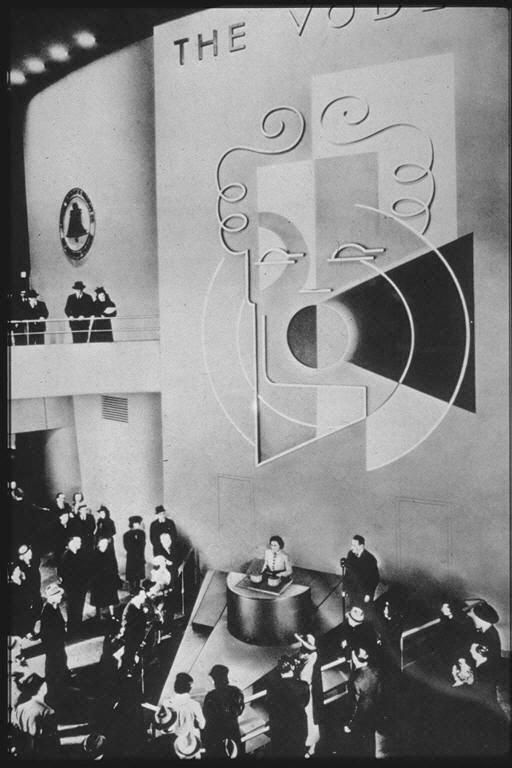
The Voder made its first public appearance in 1939 at the New York World’s Fair.

Voder Schematic

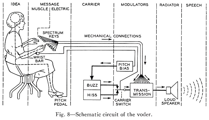
The Voder performed speech synthesis by emulating some of the behavior of the human vocal tract. It selectively fed two basic sounds, a buzz and a hiss, though a series of 10 bandpass filters. By selecting the buzzing source the machine could produce voiced vowels and nasal sounds, voiceless and fricative sounds were produced by filtering the hissing noise.

If a keyboard and pedals could be used to produce speech then so could a low bitrate digital signal. Homer Dudley, Voders creator, with the help of Alan Turing went on to contribute to SIGSALY, a compressed and encrypted speech system that successfully secured communications between the likes of Churchill and Roosevelt during the war.

Daisy

In 1961, physicist John Larry Kelly, Jr used an IBM 704 computer sing the song “Daisy”. This demo inspired one of the greatest moments in all of cinema when Arthur C. Clarke, who was visiting the lab at the time, decided that a certain HAL 9000 would serenade Dave Bowman whilst being lobotomized.

Dave
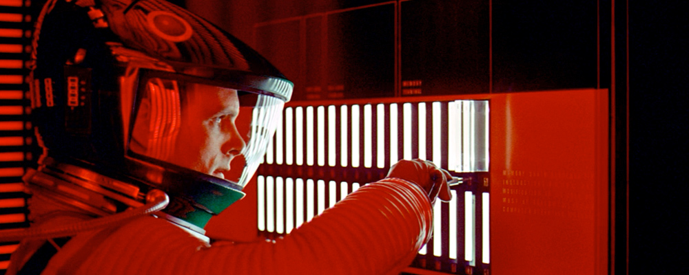
“My instructor was Mr. Langley, and he taught me to sing a song. If you’d like to hear it I can sing it for you.”

Talking Chips

By the 70s companies like Votrax were producing discrete logic speech synthesizers and text-to-speech algorithms. The United States Naval Research Laboratory, or “NRL” text-to-phoneme algorithm was developed by a collaboration between Votrax and the NRL in 1973. “Automatic Translation of English Text to Phonetics by Means of Letter-to-Sound Rules” allowed translation from arbitrary text to phonemes, the smallest units of sound in a word that makes a difference in its pronunciation and meaning. Phonetic alphabets such as ARPABET are used as a common representation of speech to program these devices.

By the end of the 70s and early 80s a variety of integrated circuit speech synthesizers have emerged. The Texas instruments’ LPC speech chip family bring the Speak and Spell to life but early versions could only play back a fixed set of words.

The Votrax SC-01, famous for its use in the arcade games like Gorf, Wizard of Wor, Q-bert (where Q-bert would swear with random phonemes) was one of the first affordable simple formant synthesizers that could produce arbitrary speech; phoneme input was rendered into sequences of formants for vowels, and filtered noise for consonants and unvoiced sounds.

Chips like the SC-01 (Alien Group Voice Box) and the GI-SPO256 (Intellivoice) started to appear in peripherals for the growing personal computer market. The stage was set for a cheaper, more versatile software alternative.

Software Automatic Mouth (SAM)

In 1982 Don’t Ask Software (now SoftVoice, Inc.) released S.A.M. The Software Automatic Mouth, a voice synthesis program for Atari, Apple and Commodore computers written by Mark Barton. At $59.95 (at least for the Atari version) it was much cheaper than the hardware alternatives. It included a text-to-phoneme converter and a phoneme-to-speech routine for the final output.

SAM used a rule based translation of text to speech that owes a lot to the NRL work from 1973. It used formant synthesis to generate sounds in a way that is efficient enough to run in the limited environments of home computers of that area. There were a few limitations: the Atari and Commodore versions needed to disable the screen while generating audio which limited the kinds of applications that could be created, and the Apple 1 bit speaker modulation sounded a little rough. But the overall effect was magical – software was talking, and in some cases, singing.

To help introduce the Macintosh in 1984 Steve Jobs turned to Mark Barton and Andy Hertzfeld to bring SAM to a new audience as MacinTalk: https://www.folklore.org/StoryView.py?project=Macintosh&story=Intro_Demo.txt

How SAM2600 Works

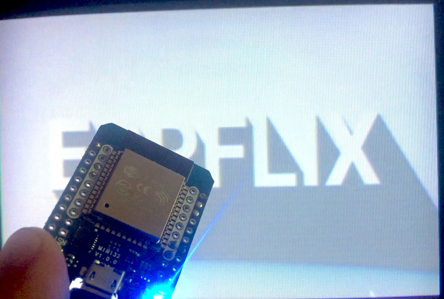
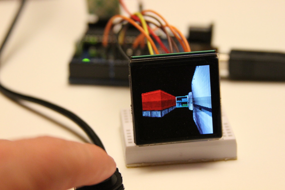
After 38 years I have finally got around to answering a question I pondered to myself in 1982 when I first heard SAM talk on my Atari 800: Could SAM run on something as constrained as an Atari 2600?

A 2600 only has 128 bytes of RAM vs 48k on the 800, a ratio of 1:384. It has a slower clock (1.19Mhz vs 1.79Mz), no disk drive etc. But it had the same CPU architecture and similar audio hardware: an exotic 4 bit DAC. Surely there was a way…..

When Sebastian Mackie created a C version of SAM from disassembled 6502 code my interest was rekindled. Although the batch generation of phonemes from text and then sound from phonemes was well beyond the memory capacity of the 2600 I realized that splitting the process and thinking of the problem more like a Voder could make something that would fit on the console.

Internally SAM has a three stage pipeline: text to phoneme, phoneme to allophone, allophone to pcm. Allophones are sounds, a phoneme is a set of such sounds (long vowels and diphthongs have two allophones, plosives often have three, other phonemes just have one).

The first two stages are rules based and have a non-trivial code footprint. If you are trying to put a game onto a 4k cartridge there isn’t a whole lot of room. But the allophone to audio stage looks a little more manageable.

Fitting into an Atari 2600

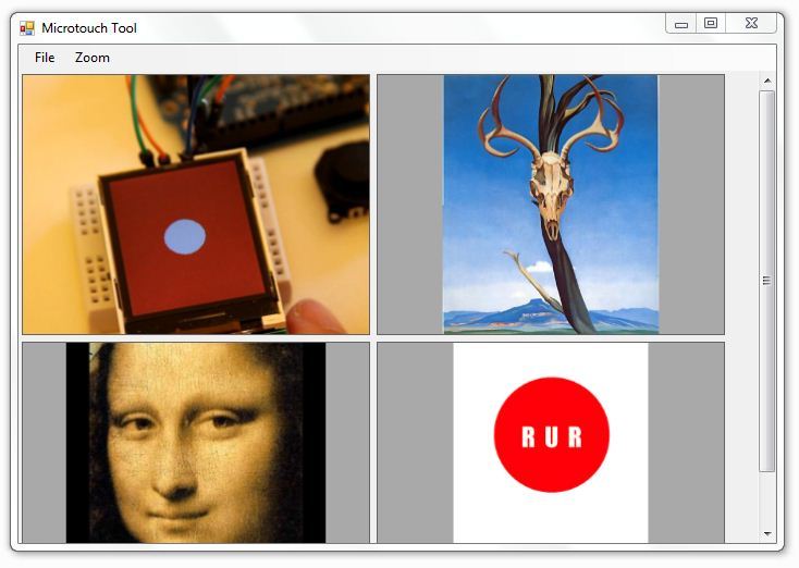
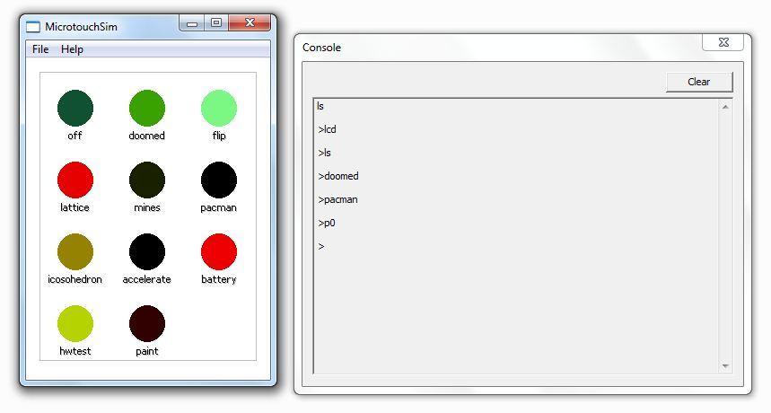
SAM2600 separates the complex rule based parts from the allophone to audio stage. The code that runs on the 2600 is analogous to playing the Voder, a compressed stream of phoneme/allophone/timing data. The complex stuff is moved to a web based authoring tool were tons on RAM and compute make it easy to create and share speech.

GUI

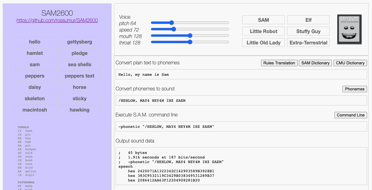
The SAM2600 Authoring Tool produces a compressed format designed to be compact but easy to interpret at runtime. Individual phoneme/allophones are encoded as two or three bytes. Pauses are encoded as 1 byte. This format encodes speech at around 25-30 bytes per second, roughly the speed of a 300 baud modem.

// Compress samples into atari runtime version
// A sample is encoded as 1,2 or 3 bytes
// Sample timing units are in VBLs so PAL and NTSC are going to be a bit different

//	0: 0x00 			end of sequence

//	0: 0x01-0x4F		formant index
//	1: run:5 mix:3 		run (how long the phoneme lasts) and mix (duration of mixing with last phoneme)

//	0: 0x50-0x7F  		silence frame count + 0x50

//	0: 0x81-0xCF		(formant index | 0x80)
//  1: pitch 			updated pitch value (f0)
//	2: run:5 mix:3 		run (how long the phoneme lasts) and mix (duration of mixing with last phoneme)

//	0: 0xD0-0xFF		escape code + 0xD0 for signaling

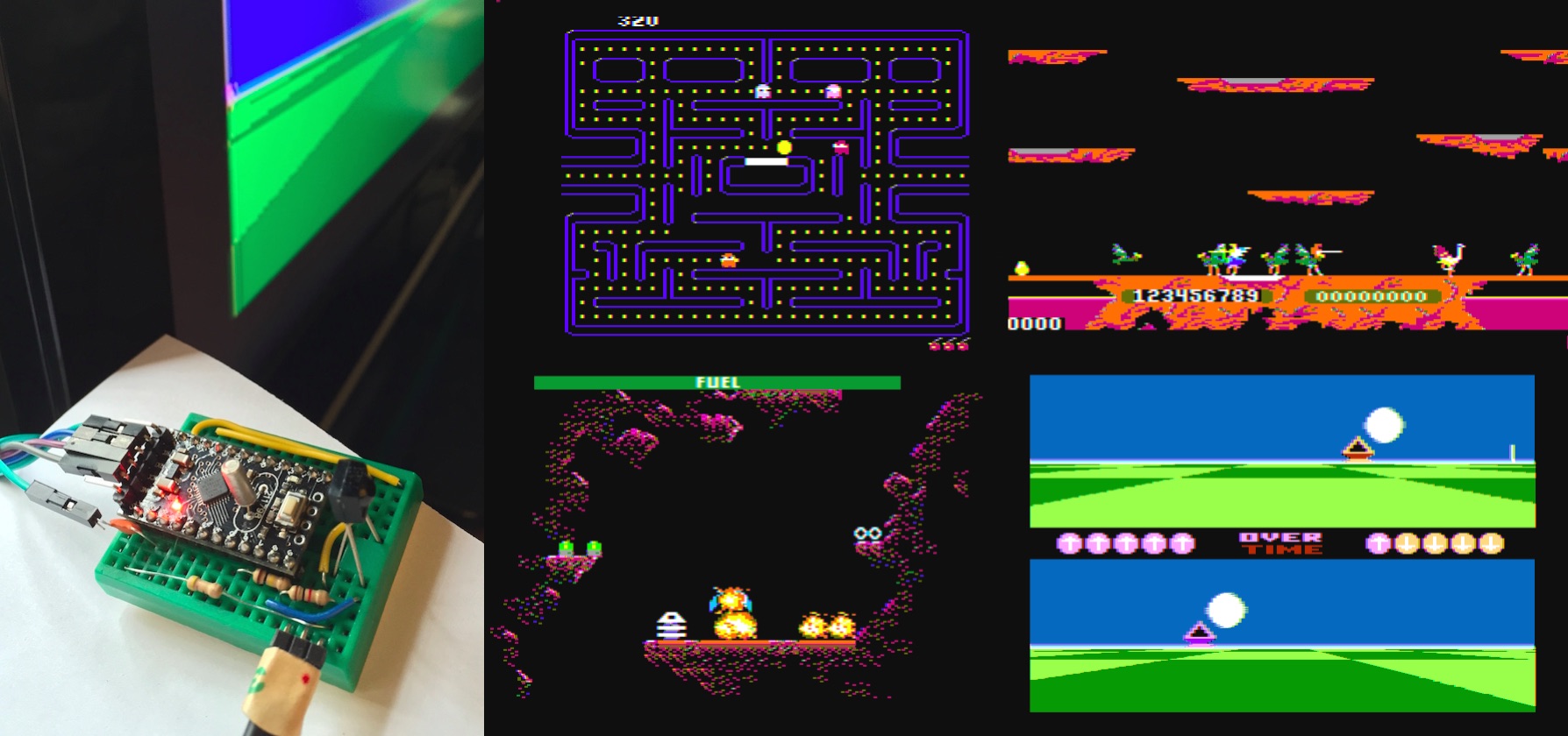
One of the delights of programming the Atari 2600 is the proximity of the code to the hardware generating the video and audio. Unlike the Atari 8 bit computers there is no DMA, interrupts or other modern conveniences that get in the way of generating real time media. I love systems like that.

The challenge is to integrate the speech engine into some other useful context (like a game) that needs to draw on the screen do some useful processing. The solution is that SAM2600 only uses every second line to generate samples (at a rate of 7860 samples/second) which is plenty for speech. Some creativity will be required operate in this mode but 2600 programmers are a scrappy bunch.

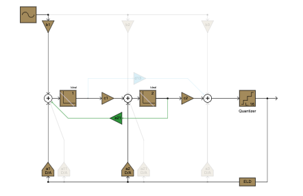
The speech engine uses a stream of phonemes that index a table of formant frequencies (f1,f2) and amplitudes (a1,a2). These four values are interpolated alongside pitch (f0) during VBL to produce smoothly varying speech. These format tables can be modified to produce voices of different gender, age and planet of origin.

If the phoneme is unvoiced (‘S’ in She Sells Sea Shells) the engine selects hardware generated noise of the appropriate frequency and volume.

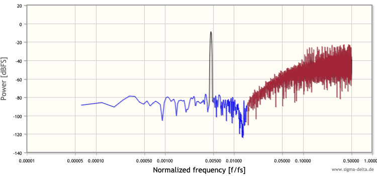
In voiced phonemes, formant frequencies are used with sinewave DDS to produce two of the three tones required for intelligible speech. The two values are summed together and output to a 4 bit DAC: the channel volume register AUDV1.

Pitch is incredibly important to reproducing intelligible speech and given we only have ~70 cycles to produce a sample, modulation of f1,f2 by the vocal cord pulse would seem impossible. SAM had a brilliant trick for this: resetting the DDS counters every pitch period produces a nice f0 buzz with very little CPU time.

It is remarkable how much SAM2600 has in common with Stewart’s work from 1922. A buzzer and two formant frequencies mixed dynamically is just about all you need.

The speech engine uses 33 bytes of RAM and 1.2k of ROM leaving up to 2.8k for speech in a 4k cartridge. This is enough for about 2 minutes of continuous unique speech, or as much as you like with fancy bank switching.

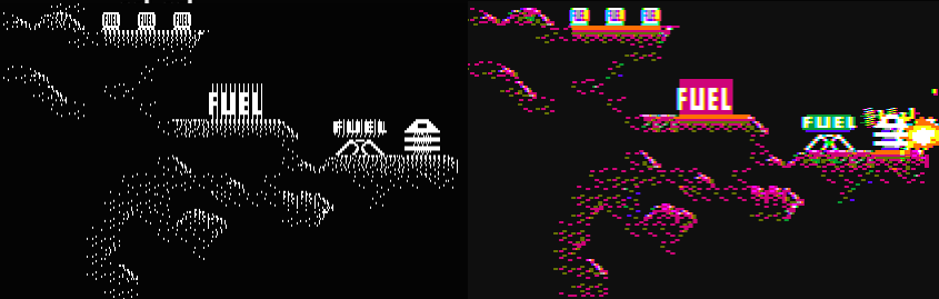
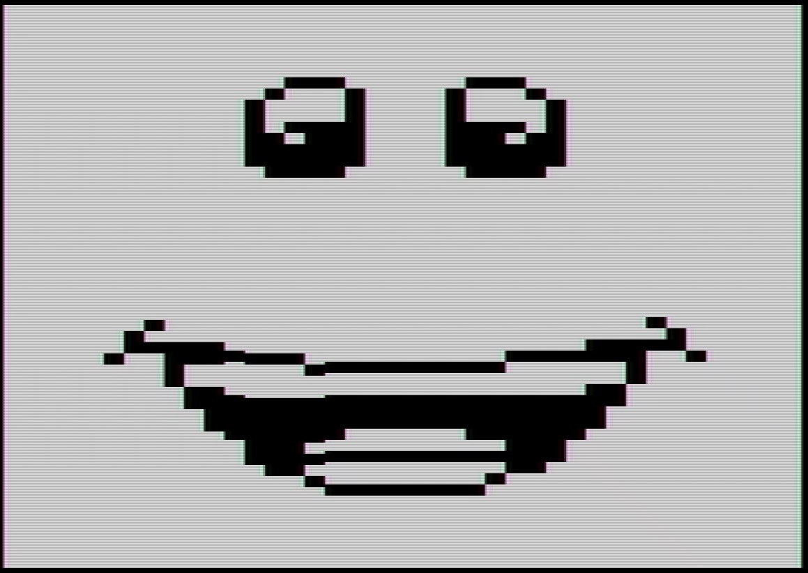
The examples use ~.5k to produce an animation that maps phonemes to mouth shapes. These mappings are far from perfect but the effect seems to work fairly well. Our brains are pretty good at filling in the blanks.

The Future

In the decades since SAM was created speech synthesis has evolved tremendously. Progress in the last couple of years has been greatly accelerated by advances in deep learning: rule based approaches and heuristics have given way to huge networks and eerily accurate results.

If someone out there has time on their hands I would love to see modern deep learning based TTS applied to the SAM2600 engine. The data format is expressive enough to produce much more accurate prosody and expressiveness than what is possible to create with rule based approaches.

Looking forward to see what folks do with this,

Rossum

http://www.rossumblog.com

ESPFLIX: A free video streaming service that runs on an ESP32

Find yourself stuck indoors during a pandemic? Why not build an open source settop box and connect to the only microcontroller powered video streaming service?

See it in action on YouTube. Source at https://github.com/rossumur/espflix.

ESPFLIX

ESPFLIX is designed to run on the ESP32 within the Arduino IDE framework. Like the ESP_8_BIT, the schematic is pretty simple:

    -----------
    |         |
    |      25 |------------------> video out
    |         |
    |      18 |---/\/\/\/----|---> audio out
    |         |     1k       |
    |         |             ---
    |  ESP32  |             --- 10nf
    |         |              |
    |         |              v gnd
    |         |
    |         |     3.3v <--+-+   IR Receiver
    |         |      gnd <--|  )  TSOP4838 etc.
    |       0 |-------------+-+       -> AppleTV remote control
    -----------

You will also need an AppleTV remote control or similar. Lots of compatible remotes on ebay for a few dollars. It is pretty easy to adapt other remotes, see ir_input.h for details.


On first boot select a WiFi access point and enter a password. If you need to change the access point at a later time hold the menu key during the splash screen to return to the access point selection screen.

Access Point Selection

Once in the top level menu scroll left and right to select something to watch. When in playback left and right on the remote will fast forward / rewind. up and down will skip forward and back by 30 seconds. menu will save the position of the current content and return you to the selection screen.

New this month on ESPFLIX

Posters of Lineup

Ok, so it is a slightly smaller collection than Netflix but still stuff that is funny/enjoyable/interesting. Big shout out to the brilliant Nina Paley for all her great work.

How It Works

Building on the NTSC/PAL software video output created for ESP_8_BIT, ESPFLIX adds video and audio codecs and a AWS streaming service to deliver a open source pastiche of Netflix.

MPEG1 Software Video Codec

In 1993, Compact Disc Digital Video was introduced. Using the MPEG1 video codec, it squeezed 74 minutes onto a CD. Earlier that year the Voyager Company had used Quicktime and the Cinepak software codec to produce the first movie ever to be released on CD-ROM: The Beatle’s Hard Days Night.

While codecs have improved in the intervening decades the MPEG1 codec uses many of the same techniques as modern codecs: transform coding, motion estimation and variable length coding of prediction residuals are still the foundations of modern codecs like H264.

The standard MPEG1 resolution of 352×240 (NTSC) or 352×288 (PAL) seems like a good match for our ESP32 video output resolution. Because MPEG1 can encode differences between frames (predicted or “P” frames) you need 2 frame buffers at this resolution. MPEG1 normally also encodes differences between past and future frames (bidirectionally predicted or “B” frames) so that means 3 buffers.

A quick bit of math on the size of these frame buffers (each encoded in YUV 4:1:1 color space) yields 352 * 288 * 3 * 1.5 = 456192 which much more memory than the ESP32 has to offer. So we need to make a few concessions. We can live without B frames: they improve overall coding performance but it is easy to create nice looking video without them. We can also reduce the vertical resolution: 1993 was still a 4:3 world, 352×192 is a fine aspect ratio for the 2020s.

Even though 352 * 192 * 2 * 1.5 = 202752 seems a lot more manageable getting a MPEG1 software codec be performant still has its challenges. You can’t just malloc contiguous buffers of that size in one piece on an ESP32. They need to be broken up into strips and all the guts of the codec that does fiddly half-pixel motion compensation has to be adjusted according. Much of this memory needs to be allocated from a pool that can only be addressed 32 bits at a time, further complicating code that needs to run as fast as possible. If the implementation of the MPEG1 decoder looks weird it is normally because it is trying to deal with aligned access and chunked allocation of the frame buffers.

SBC Software Audio Codec

SBC is a low-complexity subband codec specified by the Bluetooth Special Interest Group (SIG) for the Advanced Audio Distribution Profile (A2DP). Unlike the MP2 codec typically used along side MPEG1 video, SBC uses tiny 128 sample buffers (as opposed to 1152 for MP2). That may not sound like much but with so little memory available it made the world of difference.

I originally wrote this implementation for a Cortex M0: it works fine on that tiny device with limited memory and no hardware divider. Its low complexity is handy given the SBC audio codec runs on core 1 of the ESP32 alongside the video NTSC/PAL encoding, the IP stack and the Delta-Sigma modulator.

Delta-Sigma (ΔΣ; or Sigma-Delta, ΣΔ) Modulators

I love Delta-Sigma modulators. Despite the vigorous debate over the correct name ordinality they are a versatile tool that can be used for both high performance ADCs and DACs. A great introduction can be found at https://www.beis.de/Elektronik/DeltaSigma/DeltaSigma.html.

The ESP32 has one built into I2S0. Sadly we are using I2S0 for video generation, so we will have to generate our signal in software. To turn a 48khz, 16 bit mono PCM stream into oversampled single bit stream we will have to choose a modulator that has nice noise characteristics but is fast enough to run on already busy microcontroller.

For this design I settled on a second order cascade-of-resonators, feedback form (CRFB) delta sigma modulator running at a 32x oversample rate. 32x is normally lower than one would like (64x is more typical) but given the already tight constraints on buffering and compute it seemed like a fair tradeoff. The noise shaping is good enough to shove the quantization energy higher in the spectrum allowing the RC filter on the audio pin to do its job efficiently. For each 16 bit PCM sample we produce 32 bits that we jam into the I2S peripheral as if it were a 48khz stereo PCM stream. The resulting 1.5Mbit modulated signal sounds pretty nice once filtered.

Turns out most TVs have filtering built in, directly connecting the digital audio out pin without the RC filter will normally sound fine, just don’t look at it on a scope.

I used the great tool hosted at the University of Ulm to design the filter and calculate coefficients to get the desired noise shaping characteristics: https://www.sigma-delta.de/

Delta Sigma Design

Fig.1 CRFB 2nd Order Delta Sigma Modulator

Frequency Response

Fig.2 Noise shaping pushes quantization errors to higher frequencies

Displaying Video

Video display is similar to the ESP_8_BIT although there are a few differences. Because we have 2 frame buffers we can display one while drawing the other, or we can smoothly scroll between them during vertical blanking.

It is worth noting the DAC used to display video is 8 bit / 3.3V. We only use enough bits to get the ~1V range required for video. A voltage divider would allow us more dynamic range on the video but would require a little more assembly. At some point I will add an option to get slightly better video quality using this method.

Streaming

This all depends on the fantastic AWS infrastructure. Because we are so tight on memory (~10k left once video is running) we don’t have a lot of memory for buffering. Netflix uses many megabytes of buffering, MPEG1 systems like VideoCD needed a minimum of ~50k, we have all of 6k at our disposal. The LWIP stack that the ESP32 uses is not really optimized for streaming media. If the servers are sufficiently far way the TCP AIMD algorithm never has a chance to open the window enough to get reasonable throughput. To overcome this limitation I will offer the service through AWS Cloudfront to try and optimize the experience of those fiddling with it for as long as I can afford it.

The video files themselves are encoded with ffmpeg at around 1.5MBits. Rate control models / multiplexer don’t really work with tiny buffers so your mileage may vary. Although everything is out of spec for the most part audio and video show up at roughly the right time.

The system also produces trick mode streams for smooth fast forward and rewind plus an index that allows mapping of time from one stream to another. This index can’t fit in memory but by using http range requests we can lookup any slice of the index without loading the whole thing.

Enjoy

The ESP32 is a great little device. Kind of amazing you can create a settop box for less than the price of a remote control and that platforms like AWS enable a streaming service like this for very little time/money.

cheers,
Rossum

ESP_8_BIT: Atari 8 bit computers, NES and SMS game consoles on your TV with nothing more than a ESP32 and a sense of nostalgia

Supports NTSC/PAL color composite video output, Bluetooth Classic or IR keyboards and joysticks; just the thing when we could all use a little distraction

esp8bit

ESP_8_BIT is designed to run on the ESP32 within the Arduino IDE framework. See it in action on Youtube. Schematic is pretty simple:

    -----------
    |         |
    |      25 |------------------> video out
    |         |
    |      18 |---/\/\/\/----|---> audio out
    |         |     1k       |
    |         |             ---
    |  ESP32  |             --- 10nf
    |         |              |
    |         |              v gnd
    |         |
    |         |     3.3v <--+-+   IR Receiver
    |         |      gnd <--|  )  TSOP4838 etc.
    |       0 |-------------+-+   (Optional)
    -----------

Audio is on pin 18 by default but can be remapped.

Before you compile the sketch you have 2 choices:

//  Choose one of the video standards: PAL, NTSC
#define VIDEO_STANDARD NTSC

//  Choose one of the following emulators: EMU_NES,EMU_SMS, EMU_ATARI
#define EMULATOR EMU_ATARI

Build and run the sketch and connect to an old-timey composite input. The first time the sketch runs in will auto-populate the file system with a selection of fine old and new homebrew games and demos. This process only happens once and takes about ~20 seconds so don’t be frightened by the black screen.

The Emulated

Atari 400/800, XL, XEGS, 5200

Oh how I adore thee Atari 8 bit. 40 years on your cheery blue default background color and enigmatically wiggly built-in font still delights me. Your bizarre industrial design and giant floppy drives are the stuff of legend. Nice to see you back in this new incarnation.

Atari support is built from the venerable Atari800 emulator. Some violence was done to move structures and tables into read-only flash. It does not support machines with 128k RAM.

Enter/Exit GUI with F1. In GUI, ‘1’ or ‘2’ keys insert a disk (.atr file) into drives 1 or 2. A ‘0’ key ejects the disk. Shift + Enter will insert Basic along with the selected disk. A ‘filename.cfg’ file can be used to override default settings. i.e.
miner2049er.bin.cfg (for miner2049er.bin) would look like

-5200 -ntsc -cart-type 4 -cart

File system is mounted as the “H1” device. See https://atari800.github.io/ for more details.

Keyboard Atari
Arrow Keys Joystick 1
Left Shift Fire Button
F1 Open/Close GUI
F2 Option
F3 Select
F4 Start
F5 Warm Reset
Shift+F5 Cold Reset
F6 Help (XL/XE)
F7 Break
Keyboard Atari 5200
S Key Start
P Key Pause
R Key Reset
WiiMote (sideways) Atari
D-Pad Joysticks
A,B,1,2 Fire Buttons
Home GUI
Minus Select
Plus Start
Plus & Minus Together Warm Reset

Nintendo Entertainment System

Based on nofrendo.

Keyboard NES
Arrow Keys D-Pad
Left Shift Button A
Option Button B
Return Start
Tab Select
WiiMote (sideways) NES
Plus Start
Minus Select
A,1 Button A
B,2 Button B
Plus & Minus Together Reset

Sega Master System, Game Gear

Based on smsplus. Plays .sms (Sega Master System) and .gg (Game Gear) ROMs. Game Gear titles look a little funny in the middle of the screen, but Shinobi is still a masterpiece.

This is the same emulator with which the brilliant and prolific SpriteTM first demostrated the power of the ESP31. Jeroen is the person most responsible for making the ESP32 ecosystem a pleasure to work with.

Keyboard SMS
Arrow Keys D-Pad
Left Shift Button 1
Option Button 2
Return Start
Tab Select
WiiMote (sideways) SMS
A,1 Button 1
B,2 Button 2
Home GUI
Minus Pause
Plus Start
Plus & Minus Together Reset

How it works

Composite Video

Much as been written on generating color composite video with microcontrollers. Rickard Gunée kicked it off in 2003, with many fun variants emerging over the years. I enjoyed building the RBox in 2010 that used a Cortex M0 and a R2R DAC to generate color NTSC, then in 2015 the Arduinocade on an Arduino with upgraded crystal that used its SPI port to create the colors. Now that 2020 has given us all a little extra time at home its time to do another one.

Now that we have fancy devices like the ESP8266/ESP32 we can be a little more ambitious. We have an order of magnitude more compute, two orders of magnitude more RAM, and three orders of magnitude more storage than an Arduino. And we have lots of new exotic new peripherals to play with. Using this newfound power CNLohr pulled off an amazing 1-bit Nyquist folding trick to produce a color NTSC broadcast on an ESP8266. Bitluni clocked the ESP32’s DAC up to 13.3333Mhz and manged to create color PAL. Bitluni overview of how PAL works, his online visualization tools, his findings from spelunking around in the ESP32, and his other great projects are really worth exploring.

The principle figure of merit for generating nice looking PAL or NTSC color is the accuracy and stability of the synthesized color carrier. Bitluni’s clever technique used DDS to produce PAL carrier with ~3 DAC samples per cycle – close enough for most TVs to lock. Phase Alternate Line helps a lot here.

NTSC is a lot more fussy about phase stability, jitter and frequency of its color carrier. DAC + DDS at 13.33Mhz produces a beautiful looking waveform but very sketchy color if any on most TVs.

Turns out the ESP32 has a great tool for creating rock solid color carriers: The Audio Phase Locked Loop.

The magic of the Audio PLL

The ESP32 has a ultra-low-noise fractional-N PLL. It can be tuned to produce DAC sample rates up to ~20Mhz with very accurate frequency control:

apll
Fig.1 Audio PLL formula permits precise control over DAC frequency

Its intended use is to be able to synchronize audio sources running at slightly different frequencies but is just the thing for creating accurate color carriers.

Standard (Carrier Frequency)*4 APLL Frequency
NTSC 14.318182Mhz 14.318180Mhz
PAL 17.734475Mhz 17.734476Mhz

As you can the APLL frequencies can be tuned to be incredibly close to the desired frequencies. Now we have a DAC running at an integer multiple of the color carrier we are off to the races with stable color on NTSC and PAL. From this point it is easy to construct color palettes that map indexed color to carrier phases / amplitudes.

colorburst

Fig.1 NTSC Sync and Colorburst

The APLL is great for lots of other applications. It gives you considerably more headroom above 13.33Mhz – 20Mhz is rock solid, lots of potential for DDS/RF etc.

312.5khz_dds_20mhz

Fig.2 64 step DDS sinewave from DAC driven at 20Mhz

10mhz_dds_20mhz

Fig.3 20Mhz DAC output still looks nice and clean

No Free Lunch

Exciting though it is, the APLL has one drawback. It seems that if you use a non-integer denominator (sdm1 != 0 || smd2 != 0) in the APLL settings at high frequencies, there seems to be a clock domain conflict between the DAC and I2S. If you split the DACs and try to use the I2S_CONF_SINGLE_DATA_REG to write audio samples to the other DAC channel this conflict manifests as dropouts in both DAC outputs. I would love to know what is going on here: It might have something to do with running the DAC way out of spec. Perhaps someone at Espressif will take pity on me an let me know.

APLL / DAC video looks great but it appears we need another source of audio besides the second DAC channel.

Making noises – lots of options

There are a lot of different options to create sound with an ESP32 besides the DAC. I2S1, SPI, PWM ….

PDM

If you want to build a high quality 1-bit DAC then Pulse Density Modulation is a great choice. The ESP32 I2S0 hardware has one built-in, unfortunately we are using I2S0 for video. It is fast/easy to do your own modulation and send it out any high speed digital channel: SPI with DMA, bitbanging gpio etc. Using both SPI ports would give you stereo.

Jan Ostman has done some lovely work on this on microcontrollers large and small. Also check out Super Audio CD that used PDM right before people gave up on the idea of physical media.
PDM is used in digital mems microphones and is a great way of attaching lots of microphones to microcontrollers. You could easily attach 8 of them to a gpio port on a ESP32 and build a nice 3D beamforming microphone: just add a few CIC filters and a little delay-and-sum and off you go.

PWM

PWM is really a special case of PDM. It does not do a great job of shaping noise but for our purposes it is really convenient. With up to 16 outputs from the LED PWM hardware stereo would be no problem and it only takes a couple of lines of code to get it going. Its limited dynamic range is more than enough to reproduce those classic sounds from the 80’s.

You will want to add a simple rc filter to the output pin of either PWM or PDM to avoid becoming a tiny radio station and interfering with the nice video are producing.

Bringing it Together

The audio/video system uses a double buffered I2S DMA to send video data line by line to the DAC. The interrupt keeps time at the line rate (15720hz for NTSC, 15600hz for PAL). A single audio sample is fed to the LED PWM and a single line of video is converted from index color to phase/amplitude at each interrupt. The IR input pin is scanned and the various IR state machines advanced on changes.

This a/v pump is fed by the emulator running asynchronously producing frames of video and audio. The emulator may be running on a different core and may occasionally take longer than a frame time to produce a frame (SPI paging / FS etc). The interrupt driven pump won’t care, it just keeps emitting the last frame.

Bluetooth Classic HID

As of this writing the ESP32 IDF / Arduino does not support Bluetooth Classic input devices out of the box. ESP_8_BIT includes a minimal HCI/L2CAP/HID stack implemented on top of the VHCI api. This hid_server implementation is designed to support EDR Keyboards, WiiMotes and their peripherals. The implementation is bare bones but supports paring/reconnections and is easily separable to be used in other projects.

Big Cartridges

How do you fit a 512k game cartridge into a device that has 384k of RAM, nearly all of which is consumed with screen buffers and emulator memory?

Short answer is you don’t. When a large cart is selected it gets copied into CrapFS; an aptly named simple filesystem that takes over the app1 partition at first boot. One copied CrapFS uses esp_partition_mmap() to map the part of the partition occupied by the cartridge into the data space of the CPU.

We are using an Audio PLL to create color composite video and a LED PWM peripheral to make the audio, a Bluetooth radio or a single GPIO pin for the joysticks and keyboard, and gpio for the IR even though there is a perfectly good peripheral for that. We are using virtual memory on a microcontroller. And it all fits on a single core. Oh how I love the ESP32.

Keyboards & Controllers

ESP_8_BIT supports Bluetooth Classic/EDR keyboards and WiiMotes along with a variety of IR keyboards and joysticks.

On boot the software searches for new Bluetooth devices for 5 seconds; if the device is in pairing mode the software should find it and display its name at the bottom of the screen. Some keyboards will require you to enter a “0000” to establish the connection the first time. WiiMotes should automatically pair and reconnect. WiiMote Classic controllers are also supported.

inputdevices

A number of IR input devices are supported if to add an optional IR receiver (TSOP38238, TSOP4838 or equivalent) to pin 0. The IR Wireless Controllers from Atari Flashback 4 work well and have that classic Atari joystick feel. Retron IR controllers are supported as are WebTV keyboards that come in various guises: WebTV, MsnTV, Displayer, UltimateTV etc. They all should work just fine. A few places have the nice Philips variant new for $11.95 w/ free shipping (search for ‘SWK-8630’). If you made a ZorkDuino you will have one of these.

Time to Play

If you would like to upload your own media copy them into the appropriate subfolder named for each of the emulators in the data folder. Note that the SPIFFS filesystem is fussy about filenames, keep them short, no spaces allowed. Use ‘ESP32 Sketch Data Upload‘ from the ‘Tools’ menu to copy a prepared data folder to ESP32.

Play through the included demos. Load up your own. Write some Atari Basic masterpiece. Type in a game from an old Antic magazine. Finally get around to finishing Zork.

Code is at https://github.com/rossumur/esp_8_bit

Enjoy,

rossum


Arduinocade

Play retro color 8 bit games on your TV from an Arduino.

Arduinocade features old school color 8 bit graphics (tiles, sprites, smooth scrolling, simple 3D) and sound (4 voice wavetable synthesis). All video and audio signals are generated with three resistors, an upgraded crystal and a little software. By overclocking the Arduino to 28.6363Mhz we can directly manipulate NTSC to generate 27 simultaneous colors. An IR receiver supports a wide variety of keyboards, joysticks and remote controls.

Video of Arduinocade in action at https://www.youtube.com/watch?v=nGIujZiEu_o

Code, tools, schematics and more detail at https://github.com/rossumur/Arduinocade

Games

These games are sketches of what is possible on the Arduinocade hardware and a far from the polished pieces that inspired them.

Ballblaster

A one-on-one sports style game inspired by the brilliant 1984 game Ballblazer. This uses a simple physics model and a 2D/3D rendering pipeline to produce 60fps animation. Try and grab the ball and shoot it into your opponent’s goal.

Pacman

What can I say? pakku pakku pakku.

Jowst

Fly around on ostrich thingys. Poke each other with sticks. Nice example of using the sprite engine to generate lots of large multicolor sprites.

Caverns of Titan

Homage to the Atari classic “Caverns of Mars”. Smooth scrolling, sprites and animation.

Building the Hardware

Lots of different ways to build this beastie. The design is simple enough to build on a breadboard with a DIP Atmega328, alternatively you might want to add a 28.6363Mhz crystal to a $2 Arduino Pro Mini or even build on a custom PCB.

You will need

  • Arduino Pro Mini, Atmega328p or equivalent
  • 28.6363Mhz Crystal (from Adafruit, eBay etc)
  • RCA Audio/Video Cable (eBay)
  • 470ohm, 1k and 100k resistors
  • IR receiver TSOP38238,TSOP4838 or equivalent (Adafruit, Mouser etc)
  • IR Input device (see below)
   
        +----------------+
        |    arduino     |
        |    uno/pro     |
        |     28Mhz      |       5v <--+-+   IR Receiver
        |                |      GND <--|  )  TSOP4838
        |              8 |-------------+-+
        |                |
        |              6 |----[ 100k ]--------> AUDIO
        |                |
        |              9 |----[  1k  ]----+---> VIDEO
        |                |                |
        |              1 |----[ 470  ]----+
        |                |
        |              3 |
        |              2 |
        |                |
        +----------------+

Mini Pro

We will be upgrading the crystal/resonator on these boards from 16Mhz to 28.6363Mhz. The easiest ones to modify have the big silver cans on them. Others use a ceramic resonator which require a bit of SMD fiddling.

Custom PCB


If you want to get silly and build a custom board you can get a video console down to about the size of a quarter. Board and schematics can be found in sim/docs/eagle.

Input Devices


Retcon IR Controller, Atari Flashback 4 joysticks, Apple TV remote

A number of IR input devices are supported. The IR Wireless Controllers from Atari Flashback 4 work well and have that classic joystick feel, as do the Retron IR controllers. These can be readily found on eBay for a few bucks. The Apple TV remote is also supported by you might feel a little silly. Edit config.h to select your input of choice.

Upgrading the bootloader

If you want to use the Arduino IDE you should upgrade the bootloader to be able to work at 115200 baud with the faster crystal installed. The optiboot_atmega32_28.hex image has been rebuilt with F_CPU=28636363 and a slower watchdog reset so baud rate calculations will be correct for our overclocked device. Install the image with avrdude and your favorite ISP.

avrdude -c usbtiny -p atmega328p -e -u -U lock:w:0x3f:m -U efuse:w:0x05:m -U hfuse:w:0xDE:m -U lfuse:w:0xFF:m
avrdude -c usbtiny -p atmega328p -U flash:w:optiboot_atmega328_28Mhz.hex -U lock:w:0x0f:m

Once the modified optiboot is installed the device will behave like an Uno, so remember to select that from the boards menu in the Arduino IDE.

Using the Arduino IDE

Note:
The current code does not work correctly with Arduino IDEs later than 1.5.6. Compiler optimizations in later versions interfere with hand timed loops in the video kernels. I will fix soon.

Copy the `Arduinocade` folder into the IDE libraries folder and relaunch IDE. You should be able to open the example games from File->Examples->Arduinocade. Edit the config.h file to enable or disable the custom `BALLBLASTER_GAME` kernel.

How it works

Video

Upgrading the crystal to 28.6363Mhz allows us to run at a multiple (8x CPU clock, 4x SPI output) of the NTSC subcarrier frequency. By spitting out bits in the right pattern at the right time we can generate NTSC colorburst and different colors based on the relative phase of the pattern.

Black (0000), White (1111), gray_5 (0101) and gray_10 (1010) don’t have a chroma component; the other 12 colors do. By inserting or skipping an extra nop in rendering kernel we can select between two different phases at the start of a line yielding 12+12+(black,white,gray) = 27 simultaneous colors on screen simultaneously. You can then add more by dithering etc.

The Art of Artifacts


Left – Pixels being emitted from the TX port, Right – Colors as they appear on NTSC

Every HSYNC interrupt the cpu emits a 3.57Mhz colorburst signal then sends pixel data from carefully timed tile or RLE video kernels. These are tricky to maintain in C, as helpful compiler optimizations often alter timing in unexpected ways. They probably all need to move to asm at some point. See note above.

The higher layer code uses a RLE format (BallBlaster) or tiles to represent game content. Because we don’t have enough memory for a full frame buffer individual lines of tiles and sprites are composed in a loop that is in lock step with the HSYNC interrupt.

TileGrind is a primitive html/javascript tool for generating color tiles and sprites. It can load and save C structs and understands the nature of NTSC color phase / artifacting. Its limitations vividly recreate the frustration of early graphics editing tools.

Audio

The Audio driver has two parts. The low level kernel runs every HSYNC, stepping each of the 4 voices though it’s wavetable, mixing the sampled voices together based on their current volume and emitting a sample to the PWM/resistor single bit DAC. This corresponds to a sample rate of 15734Hz.

The high level task runs every frame at 60Hz and adjusts envelope, modulates frequency of the underlying channels etc. It is responsible for parsing data structures containing music tracks and sound effects, adjusting volume envelopes and frequencies, swapping wavetables for different instruments etc.

AudioGrind is a primitive html/javascript audio editing tool is used to convert midi files to C struct data. It can also be used to reverse engineer classic gaming sound effects using a graphical spectrogram, without which it is nearly impossible to figure out how the effects are constructed – I’m talking to you Joust.

IR input Joysticks, Keyboards etc

The GPIO attached to the IR sensor is sampled at HSYNC and fed to one of a number of IR decoders. The 15734Hz sample rate is enough to accurately parse nearly all IR protocols. For performance reasons only one is enabled at a time; check the #ifdefs in ir_input.cpp.

So enjoy

Let me know if you have some fun with it.

Cheers,
Rossum

Zorkduino

Play Zork on your TV with an Arduino.

Who doesn’t love Zork?. Who doesn’t love Arduinos? Why not grab a few cheap components and build an Arduino gadget capable of playing all the classic Infocom games on your TV from the comfort of your couch.

A few years ago I ported a Z-Machine player to a little arduino-like device. Ever since I have been meaning to get around to a project that would work on a TV with a real keyboard and once again rekindle fond memories of long nights playing Zork on my Atari 800.

You will need:

  • Arduino UNO, Pro, Pro Mini or equivalent.
  • SD card or micro SD card + breakout board (from Adafruit, eBay etc).
  • RCA A/V Cable (eBay).
  • 470ohm, 1k and 100k resistors.
  • Breadboard, wires etc.
  • WebTV or MsnTV IR Keyboard or PS2 a nasty old PS2 keyboard (eBay).
  • IR receiver TSOP38238,TSOP4838 or equivalent (Adafruit, Mouser etc).

Building it

The schematic is very simple:

        
        +----------------+           +-----------------+
        |                |           |                 |
        |             13 |-----------| SCK    micro\SD |
        |             12 |-----------| MISO   card     |
        |             11 |-----------| MOSI   module   |
        |             10 |-----------| CS              |
        |                |      5v <-|                 |
        |                |     GND <-|                 |
        |    arduino     |           +-----------------+
        |    uno/pro     |
        |                |       5v <--+-+   IR Receiver
        |                |      GND <--|  )  TSOP4838 etc.
        |              8 |-------------+-+
        |                |
        |              6 |----[ 100k ]--------> AUDIO
        |                |
        |              9 |----[  1k  ]----+---> VIDEO
        |                |                |
        |              1 |----[ 470  ]----+
        |                |
        |              3 |----------------> *PS2 CLOCK
        |              2 |----------------> *PS2 DATA
        |                |
        +----------------+

Layout on an Arduino Uno…

…and on a Mini Pro.

Just about any SD card or microsd card breakout will do. Some of the very cheap ones (<$1) don’t have 5v to 3v3 level converters and may fry your SD card so caveat emptor. As always, Adafruit has nice ones.

WebTV keyboards come in various guises: WebTV, MsnTV, Displayer, UltimateTV etc. They all should work just fine. A few places have the nice Philips variant new for $11.95 w/ free shipping (search for ‘SWK-8630’). This one comes with a nice PS2 IR receiver; more on it later.

IR receivers come in a number of different forms. You are looking for a 38khz version with a known pinout: Some have the center pin as GND, some as V+. Make sure you know what kind you have. When in doubt, Adafruit.

I like using iPhone/iPod video cables for TV projects. Because they no longer work (their MFI chips long since revoked) they are inexpensive, are labeled internally and have a strain relief grommet.

If you have an IR keyboard then good for you. If not, connect your nasty old PS2 clock and data lines to pins 3 and 2 then order an IR keyboard.

On the disk

The microsdfiles folder contains a zd.mem pagefile along with several sample games:

tutorial.z3 Introduction to interactive fiction and a little bit of Zork I

sampler1.z5
Samples of Planetfall, Infidel, and The Witness.

sampler2.z3
Samples of Zork I, Leather Goddesses of Phobos, and Trinity

minizork.z3
A nice big chunk of Zork I that was given away with the British Commodore users’ magazine “Zzap! 64” no. 67. in 1990.

Copy these files to a freshly formatted sd or microsd card. You can find lots of other Zorkduino compatible games at the Interactive Fiction Archive. Insert the card and run the zorkduino.ino sketch from the zorkduino folder. When it is all up and running, it should look like this (depending on how many games you found):

IMAGE ALT TEXT HERE

How it works

Squeezing Zork into the limited footprint of an Arduino proved to be a bit of a challenge. The code uses a port of Mark Howell and John Holder’s JZIP, a Z-machine interpreter. The Z-machine was created in 1979 to play large (100k!) adventure games on small (8K!) personal computers. Long before Java the implementors at Infocom built a virtual machine capable of paging, loading and saving complete runtime state that ran on a wide variety of CPUs. Clever stuff.

The trouble is the Arduino only has 2k of ram. The Z-machine interpreter uses 2k for its stack alone, leaving no room for dynamic memory, disk buffers, video frame buffers, avr stack and other program state. The solution is to virtualize all stack and memory accesses from the interpreter down to a 160 byte cache and a 512 byte disk buffer. Thats where the zd.mem file comes in – a megabyte or so of virtual stack, memory and save-game slots.

Virtualizing everything slows things down a bit but serendipitously makes the Arduino perform at roughly the same speed as my old Atari 800. Video needs 912 bytes for the frame buffer, leaving ~464 bytes for the avr stack and all application and interpreter state.

Video

The video is generated with a simple state machine on the Timer1 ISR. HSYNC interrupts occur at 15.73kHz and trigger state changes for video, audio and keyboard state machines.

Active video is 308×192 pixels, 38×24 8×8 charaters. Getting this resolution requires use of the UART in SPI mode running at top (8Mhz) speed to shift out pixels from either a character font (the Atari 800 default font) or a graphics font (an extravagant waste of 2k logo). Because the video is being emitted from the TX pin it is fun to open the serial monitor to watch what ntsc video looks like as text: almost at bit Matrixy.

Audio

No homage to 70’s and 80’s computing would be complete without keyboard beeps and disk thweeps. Keystrokes generate a 1000hz feedback beep, sd card writes make a 3600hz mechanical click. These sounds are generated in the video isr by toggling pin 6 after a certain number of HSYNCs.

Keyboard

WebTV IR is an unusual UART-like asych serial protocol. It runs at ~660 baud with 3.25 start bits, a 10 bit class code, 8 bit key code, parity and stop bit. Class codes are things like keyup, keydown etc. and key codes map physical keyboard layout. The video ISR counts HSYNCs between transitions on the IR data line and passes state change events to the keyboard code.

The PS2 code is pretty conventional. A good explanation is here.

Extra Credit

If you get the Philips $11.95 keyboard variant you get a PS2 IR receiver as well. The receiver can be…

  • used as-is as a PS2 keyboard connected to pins 2 and 3.
  • gutted and turned into a nice case.

I prefer the latter. The case has a nice slot in the back with a sliding door that is perfect for a microSD card. It has a nice IR window at the front and a TSOP31238 (5V center pin) IR receiver that can be harvested from the PCB. Get a cheap Pro/Mini + microsd breakout, add that iPod video cable and it looks like this:

Drop me a line at rossumur@gmail.com if you have any trouble.

cheers

rossumblog.com

p.s. The maze in minizork is not the same layout as in Zork I. I have it if you need it.

8 bit device kindles eBook fire: An e-reader for the microtouch.

With all the fuss over Kindle Fire I thought it might be fun to see if the humble 8-Bit microtouch hardware would do a servicable job as an e-reader. With a bit of fiddling it turns out to be a quite capable if not entirely practical eBook.

Ebook

There are hundreds of thousands of books available in the epub format. The format is essentially a collection html/css/jpeg files and xml metadata such as author/title/table of contents bundled into a zip file (If you want to look inside an epub file simply change ‘.epub’ extension to ‘.zip’ and double click). I thought it might be possible to build a reader for the microtouch that would directly read a standard epub but the code and memory requirements for things like jpeg/png/gif decoders, xml parsers and decompression overwhelmed the available 2.5k RAM/32k Flash. The alternative was to transcode into a format that retained all the structure of the epub in a form easily digestible by a small, 8-bit device.


The transcoding tool (epubgrider) reads standard epub format files and creates ‘.epb‘ files readable by the microtouch code. The transcoder has a rudimentary layout engine that formats and paginates the html content, mapping font sizes and styles to those appropriate for viewing on a 320×240 screen. It records and stores hyperlinks within the html and resizes and transcodes images from jpg/png/gif etc to a raw 16bit RGB format. The transcoder then packages text/images/links/fonts etc with a spatial index in a ‘.epb‘ file. The spatial index allows fast scrolling through books with thousands of pages – 8500 for the largest book I found. Fonts are stored along with book so in theory books can have any typeface they like – epubgrinder can generate anti-aliased bitmap fonts from outlines. ‘.epb‘ books can be bundled into ‘.bks‘ bookshelves. Both formats are based on ‘blob’ files, a simple hierarchical data format that is suitable for 8-bit micros with microSD cards.

The net result is a little handheld device with virtually any number of books containing any number of pages. When launched the app shows a scrolling list of available books. Touching a book opens it in the reader, touching the right edge scrolls by page, touching the black bar at the bottom returns to the book list and saves your place in the book. The reader supports illustrations, hyperlinks within books for navigation and footnotes.


As always code is posted at https://github.com/rossumur/microtouch. The epubgrinder tool is based on the QT framework, contains a microtouch simulator and runs on Windows, Mac and Linux. There are a number of interesting .epb books and .bks bookshelves in the microSD folder and in the books.zip file in the tools directory.


If you don’t want to build your own microtouch, the lovely folks at adafruit will sell you a prebuilt one. 


until next time,

Rossum


A Little Atari 810 Disk Drive

A tiny working model of a retro computing icon offers a blend of nostalgia and sillyness.


Booting

My first computer was an Atari 400. My first disk drive was the magnificent Atari 810. Overwhelmed by a recent wave of nostalgia from playing Zork for the first time in 30 years I have built a working model of an Atari 810 that uses 8Gig microSD cards instead of 5 1/4 inch floppies to emulate up to 8 drives. Maintaining the relative dimensions of drive to media, the model is somewhat smaller than the original.

Ontop
Relativesizes

Some numbers

The original 810 managed 90k per disk and had a volume of about 30,000 cm3. Assuming a 8Gig card the new version can store about 90,000 disks and at 5 cm3 only takes up 0.000167 times as much space. So it is a lot bigger and a lot smaller. Progress eh?

How it works

The Atari 810 (and subsequent 1050) drives are “smart” serial peripherals. The Atari OS communicates drives, printers, modems and devices using the SIO (“Serial Input/Output”) protocol. SIO devices connected to the Atari with a chunky 13 pin connector.

Sio

The Atari addresses 5 bytes commands to peripherals by lowering pin 7 (Command) and transmitting 19200 baud asynch serial on pin 5 (Data Out). If the peripheral recognises the command (‘1′,’R’,1,0 for a read from disk 1, for example) it acknowleges the command and responds with data on pin 3 (Data In) at a pokey 19200 baud by default. Pin 10 can supply 50ma of 5v.

Sioread

Hardware

The hardware is pretty simple: a LPC1114 microcontroller, a microSD slot, a 3v3 regulator, a led and some caps. I used the 1114 because they are cheap and I had them lying around after building the Wikipedia reader: just about any 3v3 micro with SPI and a UART would also work fine.

Schematic
Boardandcase
Beforepainting

The enclosure is a 3D print from Shapeways. This is the first time I have used them and I have to say I was delighted bt the experience. My inexperience in 3D modeling is evident but Shapeways sent me a lovely collection of little enclosures in various materials. I tried to make it as small as possible and still accomodate the microSD card. Testors enamel completed the look (make sure you mix in some olive with the light tan and cream).

Model

Software

The microcontroller code emulates up to 8 Atari drives. At power on it checks for a microSD card, mounts a Fat16 or Fat32 file system and scans the card for .ATR and .XFD disk image files commonly used with Atari emulators. It also looks for XEX files which are Atari executables, another emulator mainstay. The code then “inserts”  the BOOT.RUR image into drive 1 and waits for the Atari to start sending commands during bootup.

BOOT.RUR is a UI app written in C and compiled with cc65. Because the drive has no input or display we use this app running on the Atari to select disk images or applications. Cursor keys select the image or xex application, moving off the left or the right edge of the screen will page the list. Keys ‘1’ …’8′ will insert the selected item into drives ‘1’..’8′. The space bar will eject the disk, the return key will boot the selected image or xex. If an xex is selected, the firmware will synthesize a kboot disk image to load and execute it.

Incontext
Screen

It is electrically possible to write an Atari app that can reflash the firmware but so far this is left as an exercise to the reader. The board pinout happens to be the same as a FTDI serial cable so inital firmware downloads can happen through FlashMagic.

As noted earlier, 19200 baud is pretty pokey by modern standards. Other drive and dos vendors came up with various tricks to make the serial run at 38400 or 57600 or beyond. This board supports a common 57600 baud mode so if you tire of the nostalgic thweep-thweep-thweep you can speed things up a bit by using MyPicodos or similar.

There are lots of good commercial and open source emulators and serial cables that are much more complete (and a little more practical) than this one. I am amazed at the continuing innovation on this platform: check out Yoomp and Crownland and compare them to titles released in the 80s.

3D model, PCB, schematics, NXP and Atari code on github shortly.

3D model, PCB, schematics, NXP and Atari code at https://github.com/rossumur/littleatari810

Until next time,

Rossum


Zork for the Microtouch.

When I was a boy I burned (and listened to) much midnight oil playing Zork and many other Infocom text adventures hunched over my Atari 800. I have never forgotten profound delights of the exploring the darker regions of the Great Underground Empire: clever puzzles, lurking grues and snarking 90k disk drives.

It is hard to believe it has been 30 years since I first played Zork. To mark the occasion I have ported a Z-machine interpreter to the Microtouch

Photo

Playing Zork 1 on a microtouch in the dark. I am likely to be eaten by a grue.

The Z-machine was created in 1979 to play large (100k!) adventure games on small (8K!) personal computers. Long before the Java the implementors at Infocom built a virtual machine capable of paging, loading and saving complete runtime state that ran on a wide variety of CPUs. Pretty sophisticated stuff for microcomputers 30 years ago.

Infocom published the most enduring works of interactive fiction; if you have not played one of these beginning to end you are really missing one of the great joys of computer gaming. Since building the microtouch version I have replayed the three Zorks, Trinity and Hitchhikers Guide and can’t understand why anyone would waste their time with the crap on facebook when these gems are out there.

The brilliant sprite ran Zork on an AVR the hard way; by implementing a CP/M emulator and running the Zork CP/M binary. His approach used an external 128k of DRAM, a luxury not available on the microtouch. Also UI (touchscreens, pixels etc) has progressed a bit since the days of CP/M so I took a slightly different approach: the code is based on a cut down version of frotz, the gold standard for z-machine interpreters. I was forced to remove support for the V6 “graphic” games to fit in the 32k flash limit of the microtouch. No great loss here, the text-only adventures were Infocom’s finest.

Because the microtouch only has 2.5k of memory, all Z-machine memory is virtual, including its stack. 3 layers of caching of different granularities were required to get reasonable performance. A page file on the microSD card (“p.pge”) acts as its backing store. By default the app loads “game.z5” game but will play most non v6 games: just change their name and copy to the microSD.

The bad news is that the code is too big to fit on microtouch with the bootloader. At 32k it needs to be programmed with an ISP. I will need to abandon frotz and reimplement with more AVR friendly code to shrink it to the size of a “normal” microtouch app. The hexfile, pagefile and a game are posted here. Copy “game.z5” and “p.pge” to microSD card, burn hex file with an ISP and enjoy. Remember the app supports save, restore and scrollback. Once you get to the barrow, you can find lots of other games here.

Until next time,

Rossum


Tardy update:

Finally posted source for Microtouch zork/frotz at https://github.com/rossumur/microtouch .

A 28k version with an icky fonts and a 31k with a nice font can be built with ‘make zork’ and ‘make zorkcleartype’. Enjoy.


microtouch from adafruit

Good news for those who always wanted a microtouch but didn’t have the time to build one: they are now available from the nice folks at adafruit. If you get one be sure to use the “rossum” coupon code at checkout for a 10% discount.

Microtouch_lrg


This version is powered by the delightful atmega32u4. It features a 320×240 pixel touchscreen, an accelerometer, full speed usb, a microsd card reader and a support for a lithium ion battery.

It has an application framework of sorts and it is possible to run a variety of applications with varying degrees of utility. Possibilites are bounded only by your imagination (and the 8 bit cpu + 2.5k of RAM). Tools support includes a PC simulator and a live sampling profiler. Code at https://github.com/rossumur/microtouch.

Building an App

Create HelloApp.cpp in apps/demos:

#include "Platform.h"

    class HelloState
    {
    public:
        int OnEvent(Event* e)
        {
            switch (e->Type)
            {
                case Event::OpenApp:
                    Graphics.DrawString("hello",110,100,0);
                    break;
                default:
                    ;
            }
            return 0;
        }
    };

    INSTALL_APP(hello,HelloState);

Build, Flash and test. You should get a little app that says ‘hello’ and never quits.

Ok. What is going on here? Microtouch as an application framework of sorts that allows multiple applications to be built into the firmware. An application is ‘installed’ with the INSTALL_APP macro: the first parameter is the name that will appear in the shell, the second defines a c++ object that maintains the applications state.

The framework (Shell.cpp) sends events to the app thorugh the OnEvent method; in this example the app draws “hello” on the OpenApp event which will always be the first event an app will see. The most common events come from the touch screen: TouchDown, TouchMove and TouchUp.

Because there is only 2k of RAM in this device we really don’t have the luxury of things like memory managers. The applications state is all the heap it will ever know; its maximum size is defined by MAX_APP_BUFFER in Platform.h and is set to 768 bytes by default. If the app state is larger thanMAX_APP_BUFFER then the application won’t be visible in the ShellApp.

Lets try a slightly more complicated version:

class HelloState
    {
    public:
        void Draw(int x, int y, int color)
        {
            Graphics.DrawString("Hello",x-10,y-6,color);
        }

        int OnEvent(Event* e)
        {
            switch (e->Type)
            {
                case Event::OpenApp:
                    Draw(120,160,0);
                    break;

                case Event::TouchDown:
                    if (e->Touch->y > 320)
                        return -1;      // Quit

                case Event::TouchMove:
                    Draw(e->Touch->x,e->Touch->y,RandomBits(1));
                    break;
                default:
                    ;
            }
            return 0;
        }
    };

    INSTALL_APP(hello,HelloState);

Now we can scrawl lots of randomly colored hellos over the screen and we can even quit by touching the bottom of the screen. The Graphics.h api is fairly self explanatory: it uses 5:6:5 RGB color and supports circles, rectangles and blitting as well as text.

Stdout is connected to the USB serial port so feel free to use printf for debugging.

Sample Applications

There are a number of example applications that exercise various parts of system. They don’t all fit in the device at the same time. The APPLICATIONS path in the Makefile defines which apps get built into the firmware.

Shell

The shell is the Microtouch equivalent of the Finder or Explorer. It displays a list of installed apps and files found on the microSD card, and is responsible for lauching apps and delegating file opening to the View app. It also has code for a simple serial console:

  • ls – list files on microSD if present
  • p1/p0 – turn profiling on/off
  • lcd – dump lcd registers
  • appname – launch appname if installed

Off

The simplest app. It turns the Microtouch off unless it is plugged into USB. The Microtouch will turn itself off after 5 minutes of inactivity so you don’t absolutely need this one, but I find it somehow comforting.

Calibrate

Calibrates touchscreen and stores calibration data in EEPROM. You probably will only need to run this app once if at all. Click in the red circles with a stylus until the application is satisfied with the consistency of the clicks. If you have a shattered touchscreen this app may give up after half a dozen attempts.

View

Displays files with inertial scrolling, currently IM2 files created with the MicrotouchTool are supported.

HWTest

Exercises major hardware components including touchscreen, accelerometer, microSD and backlight.

Accelerate

Accelerometer demo draws XYZ values and bounces a ball depending on the orientation of the device.

View

Displays files with inertial scrolling, currently IM2 files created with the MicrotouchTool are supported.

3D

The classic 3D Microtouch engine with accelerometer support. Tilt the device to move the object, touch the screen to select diffent platonic solids.

Pacman

Omage to the greatest game ever written, demonstrates a technique for flicker free sprites at >60Fps.

Doomed

A simple raycasting demo. Touchscreen controls speed and direction of movement. Despite the humble 8 bittyness of the CPU it manages 25fps. Play with it until you find the red wall.

Flip

Try and make all the dots the same color by touching to flip a pattern of 5. I find it bloody hard, I have only managed to complete it once. Could someone please publish a deterministic solution?

Lattice

Graphics demo generates a nice infinite mesh. Looks like it is complex 3D engine with lighting, shading and geometry. It isn’t.

Mines

Click. Click. Boom.

Paint

Fingerpainting with touchscreen. Press harder for a bigger brush, select one of three brushes:

  • Cycle Chroma
  • Cycle Luminance
  • Color from accelerometer XYZ

Tools

Microtouch Tool

Microtouchtool

A simple tool to create IM2 slideshow files from jpg,png or other image files. Add as many images as you like, right click to change background, image fit or remove and image. Drag to reorder. when you are satisfied save the image to a microSD card and open from the Microtouch Shell.

Microtouch Profiler

Profiler

This tool is a GUI for the built-in sampling profiler. To use:

  1. Connect Microtouch to USB
  2. Make sure the Shell is running on the Microtouch
  3. Launch MicrotouchProfiler.exe
  4. File/Open the .lss listing file that was generated when the .hex file was built
  5. Launch the target Microtouch app

The left panel displays a list of modules sorted by activity. The right panel shows the .lss file which is a mixture of source and assembly plus red bars hiliting hotspots in the code. Click on a module to move to its start in the lss file.

The built-in profiler works by sampling the PC from a timer ISR and printing it over the USB serial. If you like hexidecimal numbers you can turn the profiler on and off by typing ‘p1’ and ‘p0’ in the console.

Microtouch Simulator

Microtouchsim

A Win32 based simulator for developing Microtouch applications without the actual hardware. Simulation is pixel accurate and includes a console window that emulates usb serial stdio. The accelerometer is emulated by a series sine waves of varing period, touch pressure is selected with keys ‘1’ thru ‘9’ CPU performance is not accurately emulated.


Three OLEDs

There are a number of cheap and adorable OLED displays appearing on ebay and elsewhere. But their parallel interfaces, enigmatic driver ics and funny voltage requirements make them tricky to use. These breakout boards make it easy to connect an oled to an Arduino or any other device with a SPI interface.

Img_6990

Interfacing

All of these screens have lots of pins. Most breakout boards dutifully provide all those pins to the outside world which leads to lots of wiring up and few unused GPIO ports. Fortunately these screens can be configured to use a SPI interface saving lots of pins.

SPI has a bad rap of being slow when it comes to displays. With a bit of fiddling it is possible to get 500k pixels per second from a Arduino Duemilanove which is more than enough perf for these small screens: >30fps on 128×128.

The job of converting from 5v GPIO to 3v3 is handled by a octal buffer (74AHC244 or equivalent). They are cheap, small and a lot easier to assemble that a bunch of resistors. If you are using 3v3 IO then leave the octal buffer unstuffed and use the 3v3 holes.

Power

OLEDs require a 12v-16v supply. Although 2 out of the 3 screens actually have ‘built in’ DC-DC converters they still need external components to generate the required voltages. These components are often fussy or inefficient and I usually just roll my own. Here I have used a FAN5331 boost converter. It isn’t expensive and because it switches at 1.6Mhz you can use a small 10uh inductor which is handy of you are cramming parts onto a small board.

The Screens

The first screen is a monochrome (actually blue) 1 bit per pixel 128×32 display based on a SSD1303 controller. These are usually $5-$8 on ebay although I have seen them in china for < $2. Because this screen is only 1bpp we can afford an actual 512 byte frame buffer on the Arduino code. Of course you don’t need to use a frame buffer if you don’t want to.

The second screen is 96×64 and has 65k colors. It is based on the SSD1332 and comes in 0.8mm and 0.7mm pin pitch versions. They are $6-$7 on ebay, < $2 in china and show up as caller id screens in lots of phones and in some small mp3 players. If you see a small color OLED with a 31 pin connector it is usually a SSD1332. This controller has hardware accelerated fills and line drawing (<1ms to fill a screen) which could save you some perf and power if you do that sort of thing.

The third screen is my absolute favorite. It is a 128×128 pixel 262k color Samsung PM12FC001B that uses a LD50T6160 controller. These show up as spares every now and then on taobao. They are found in lots of OLED digital picture frames and several Samsung YP MP3 players. The demo shows a little Wolfenstein thing running on a Arduino.

A note about the video. OLEDs don’t look very nice on video due to their use of PWM. I assure you these look much nicer in person; crisp high contrast images on all three.

Code, schematics and pcbs posted at https://sourceforge.net/projects/smartlcd/files/ (threeOleds.zip). The OLEDs and smartLCDs will converge into something a little more coherent in the near future.

Until next time,

Rossum